|
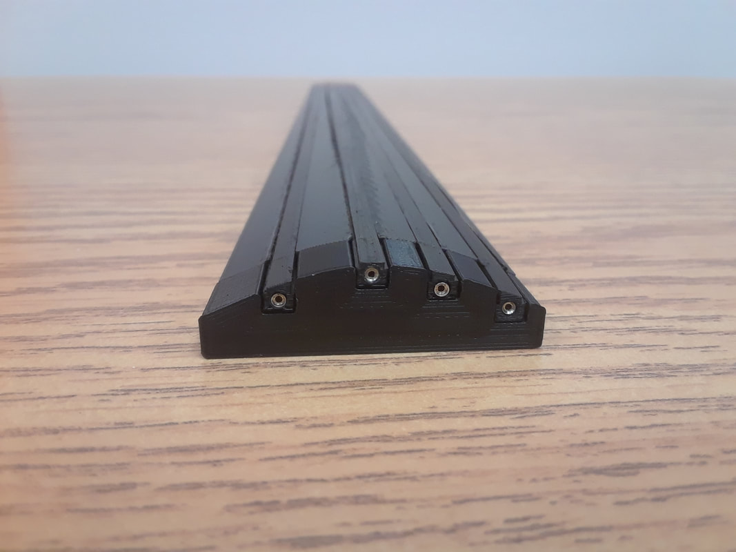
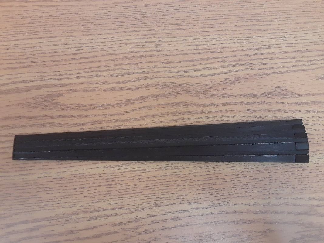
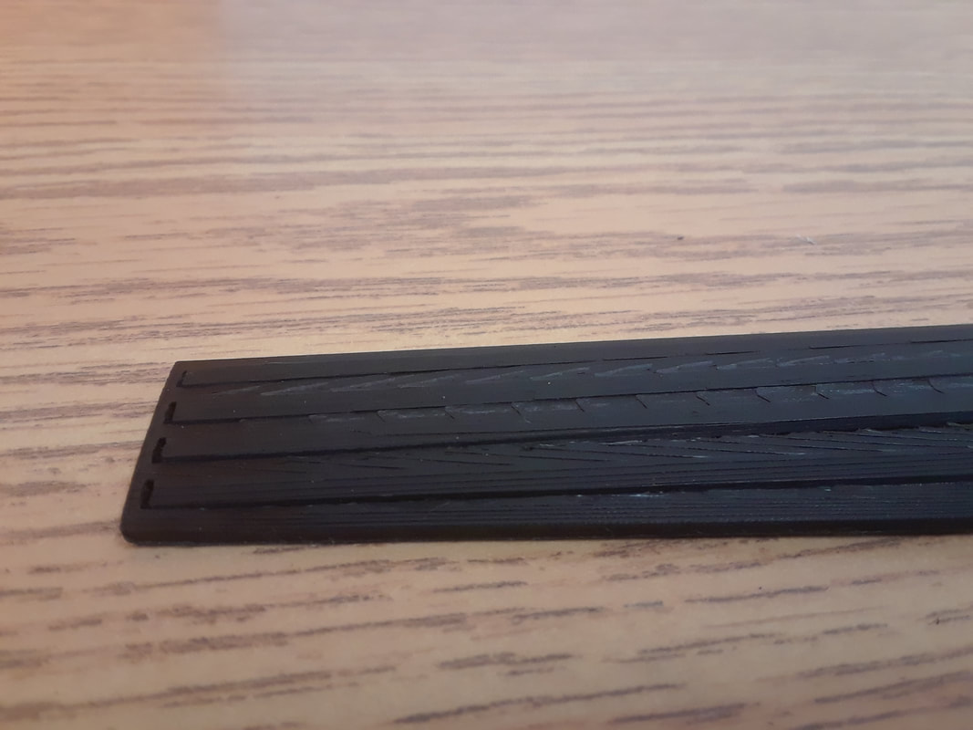
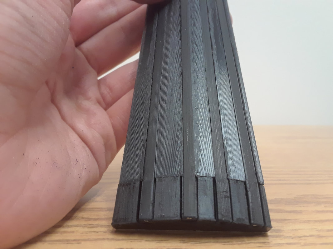
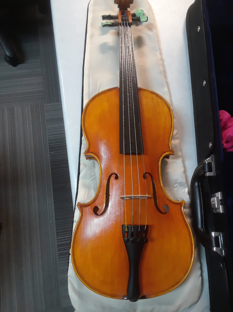
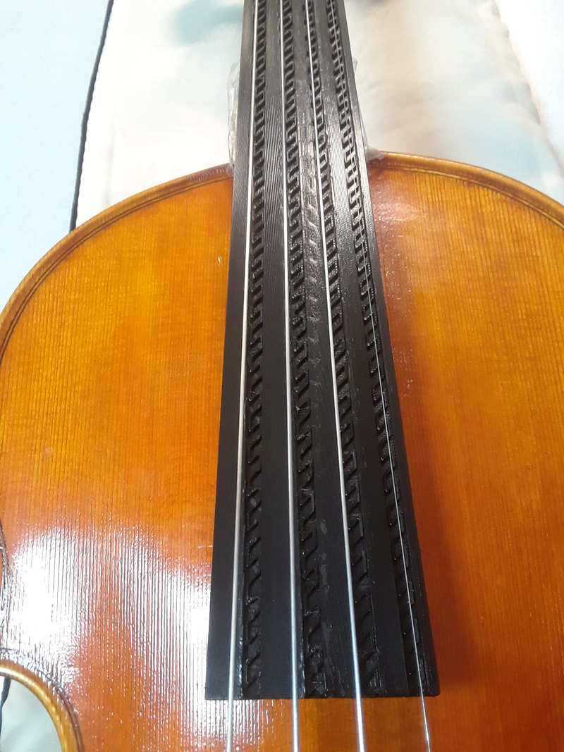
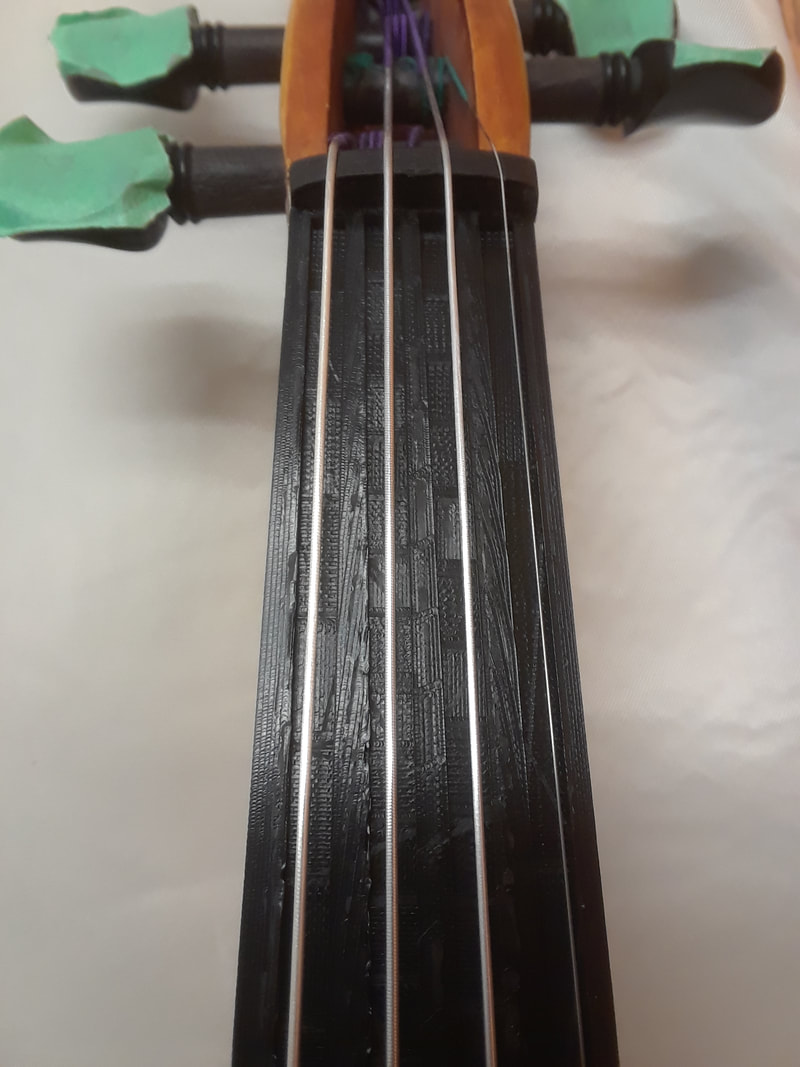
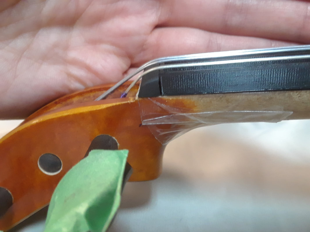
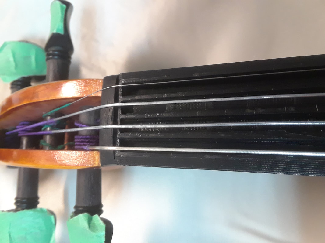
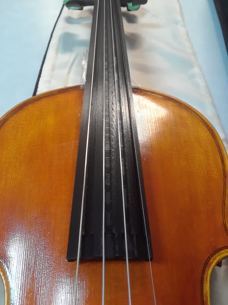
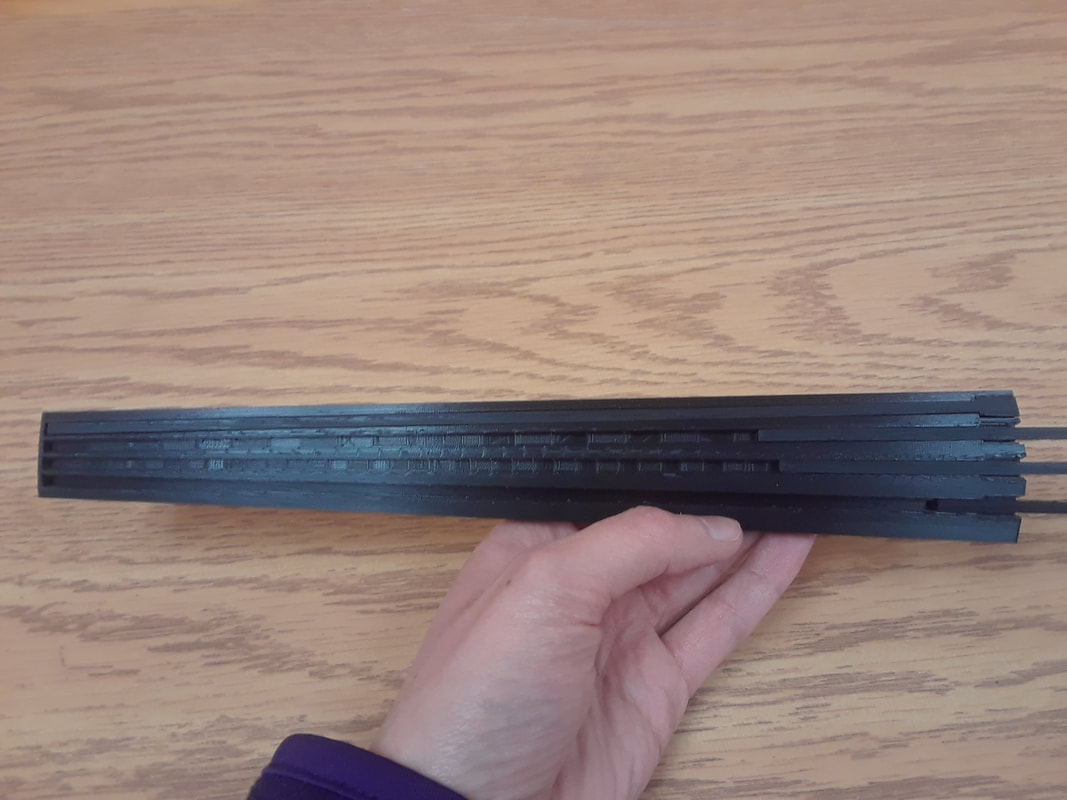
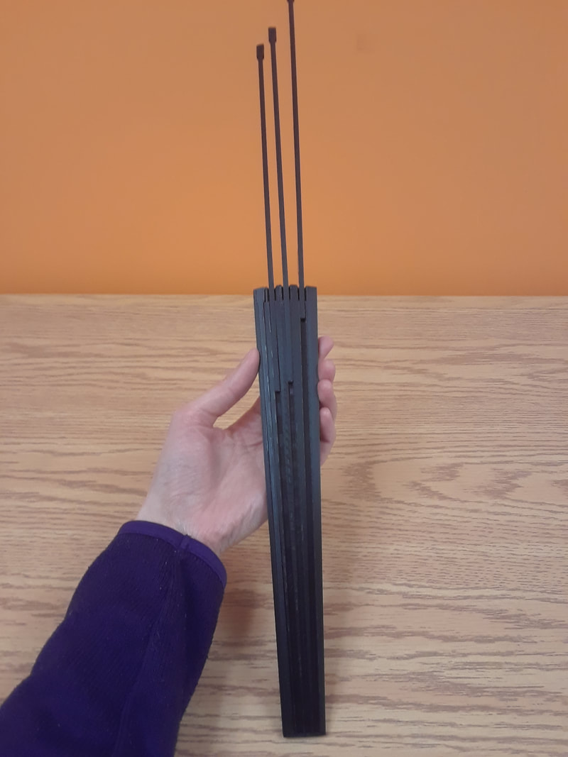
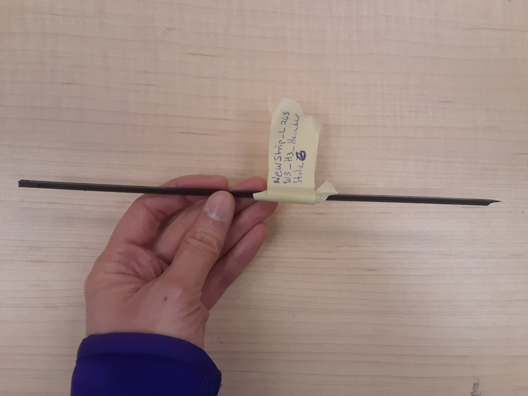
I finally finished the first ebony method fingerboard! Hopefully I won’t do anything to mess it up… I made the header holes tighter, so they don’t need glue to stay in. Just need to be extra careful when unplugging them that they don’t get pulled out. I sanded the top so that the strips are flush with the surface.
0 Comments
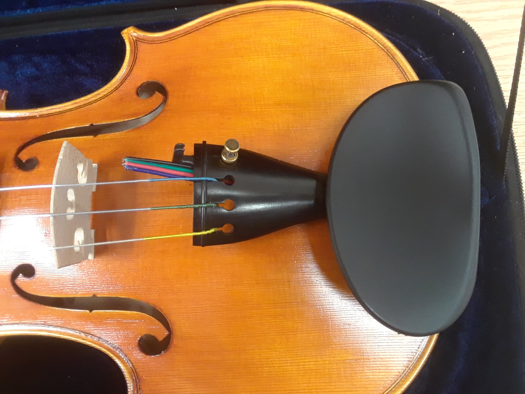
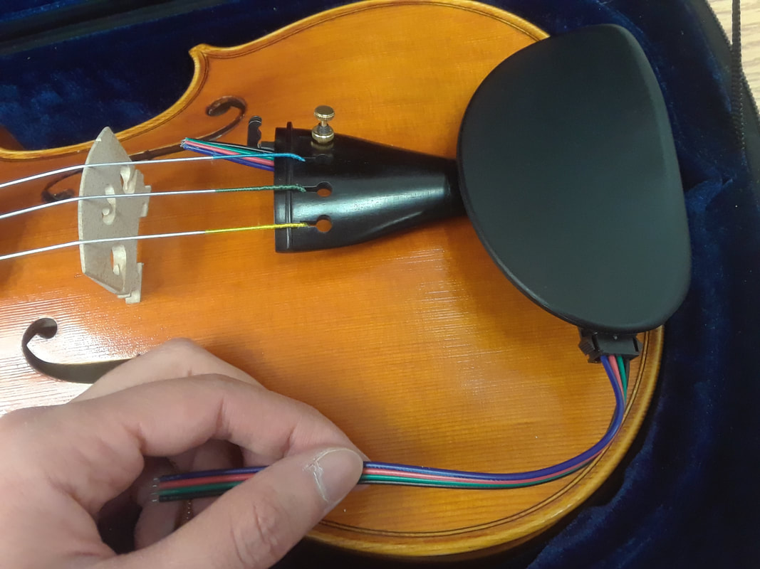
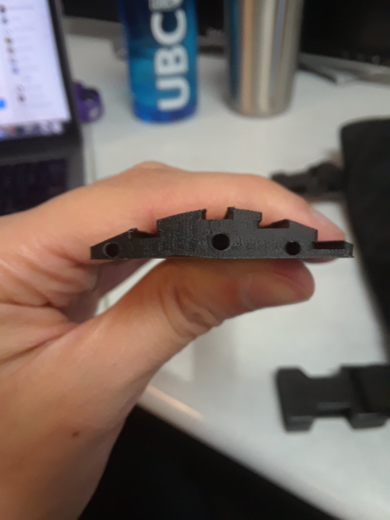
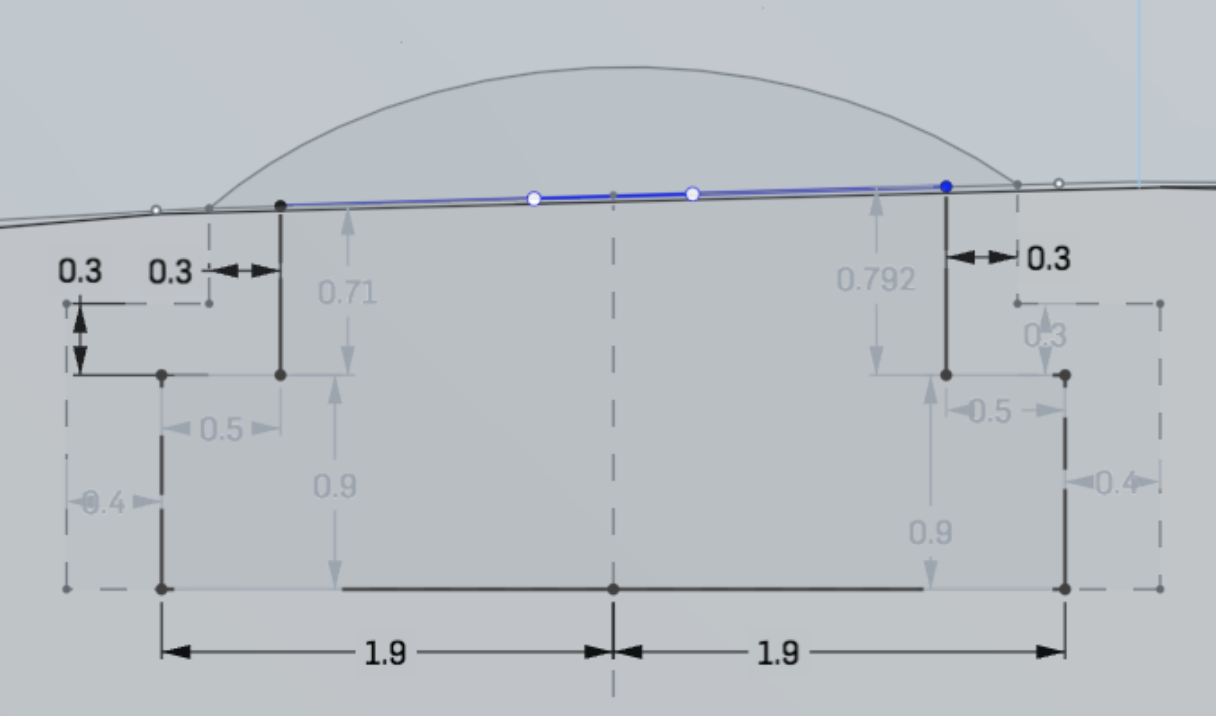
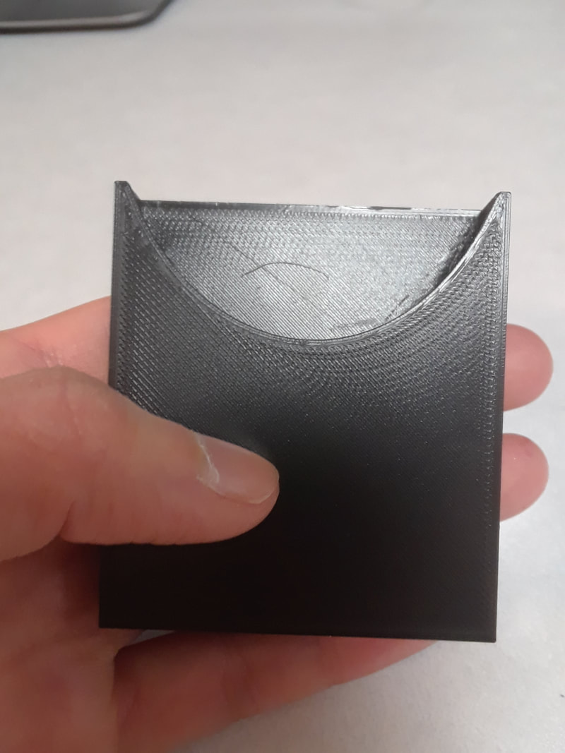
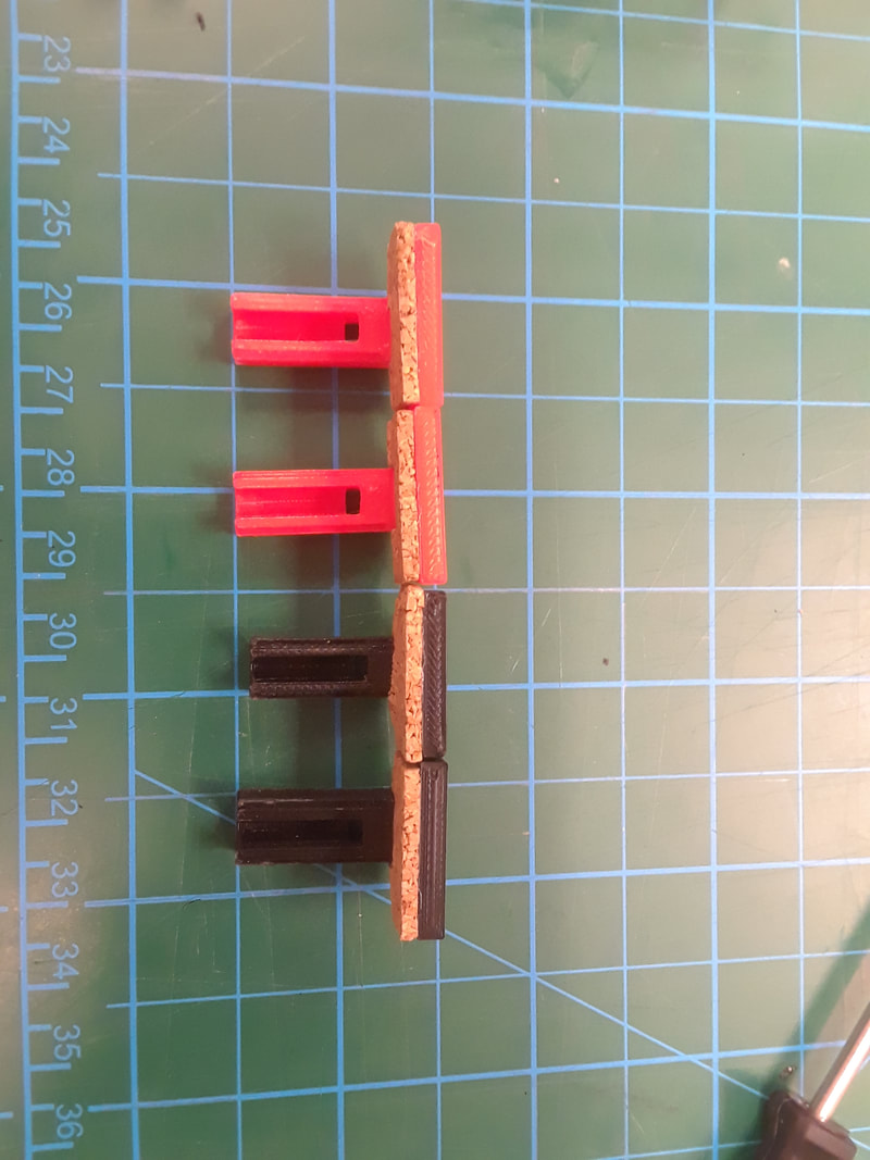
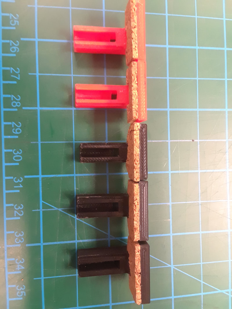
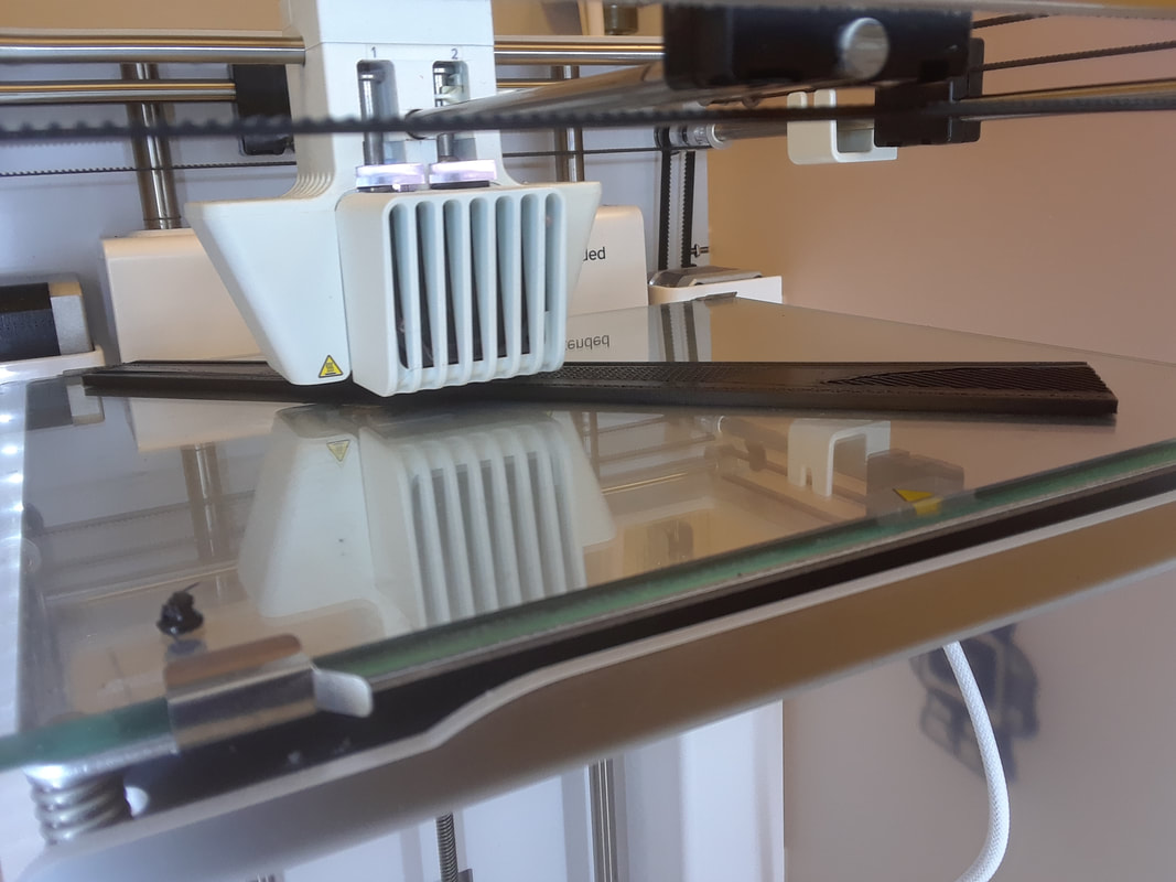
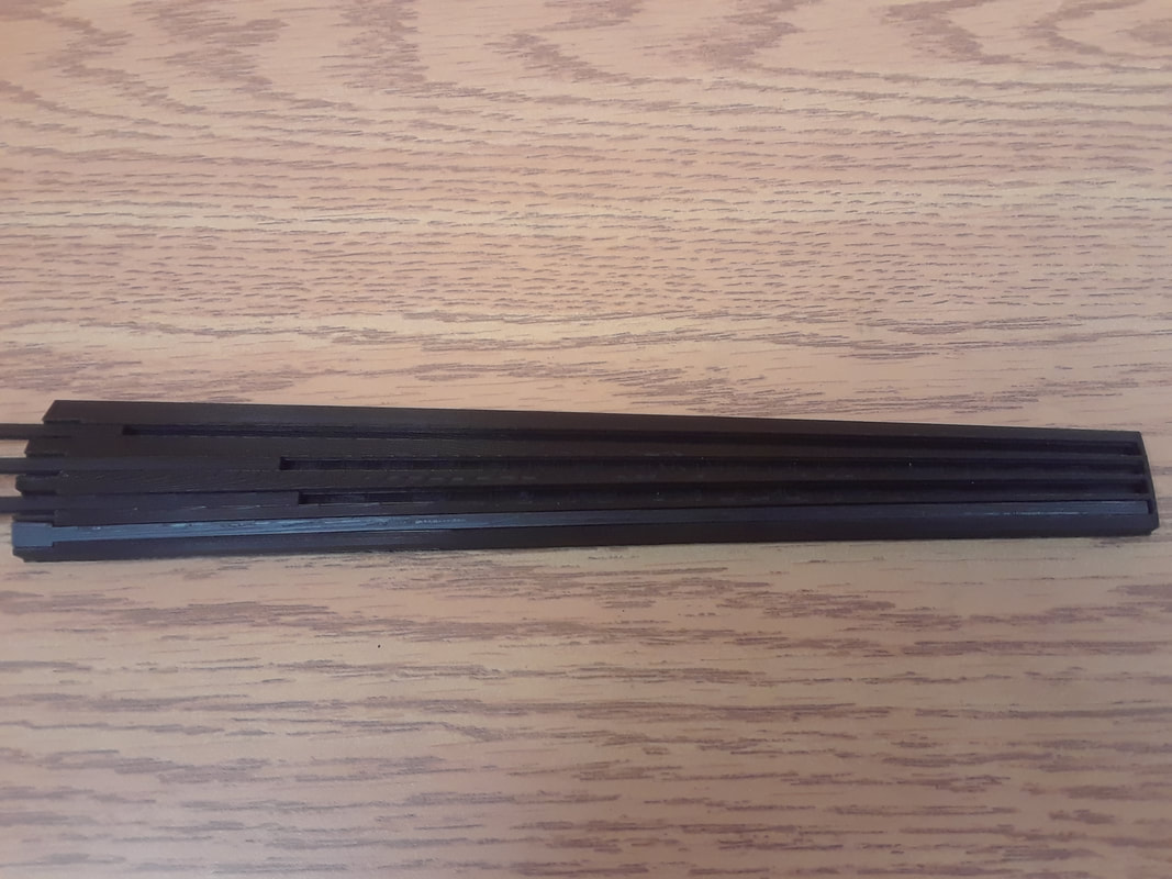
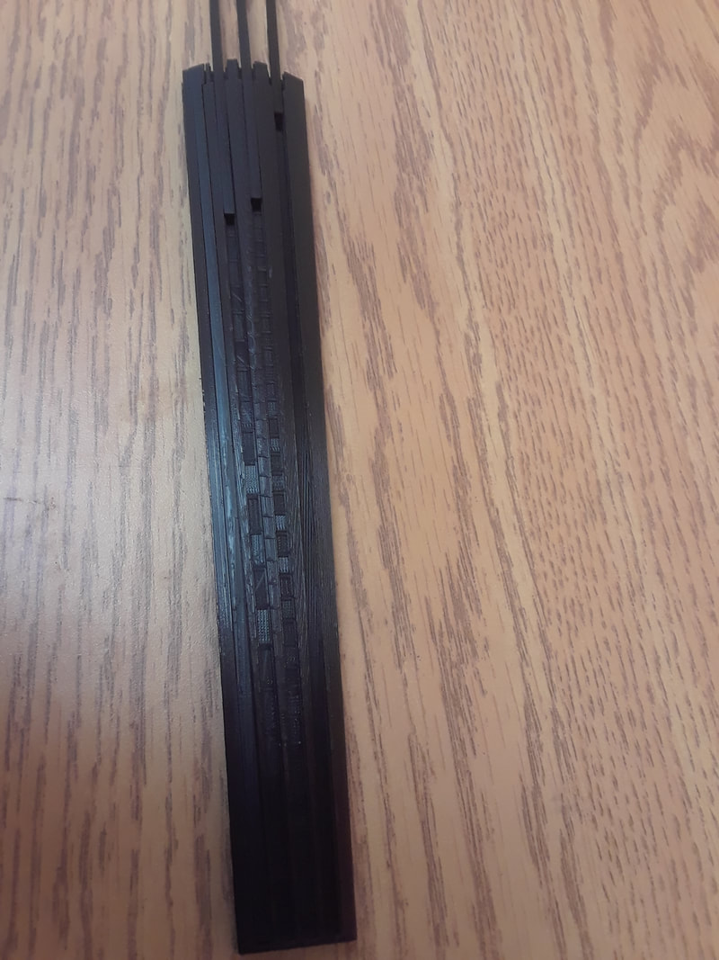
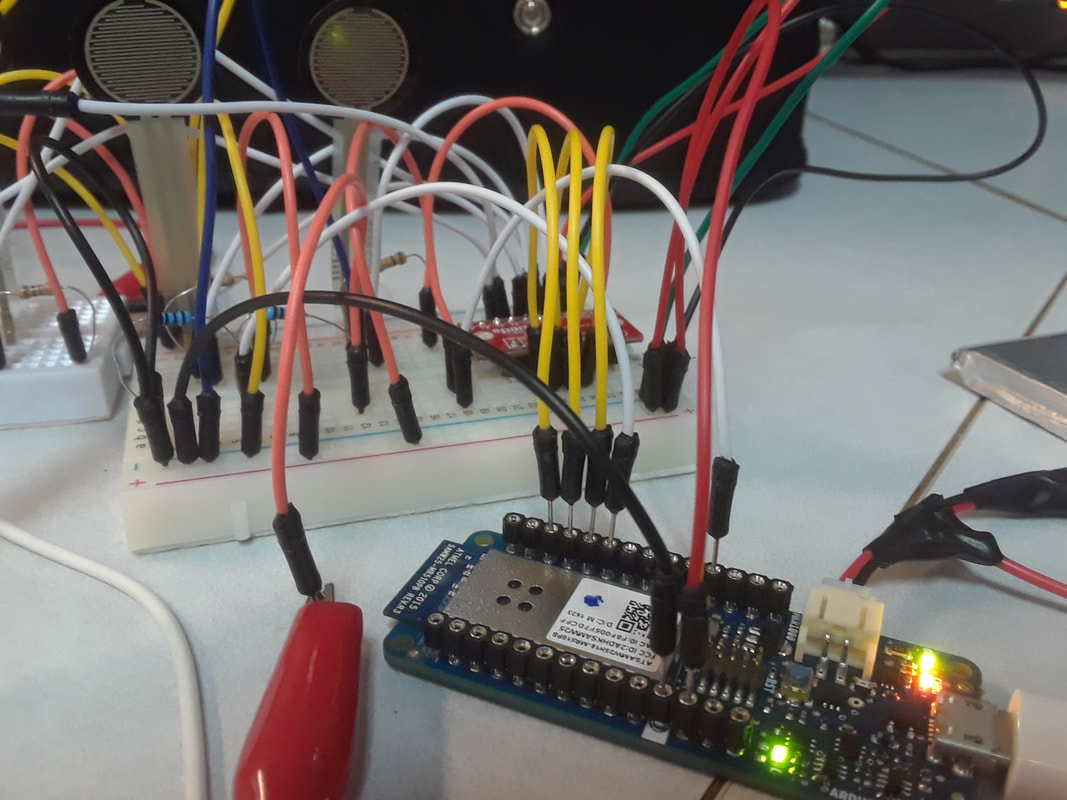
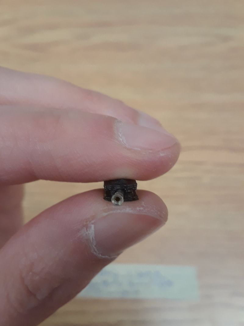
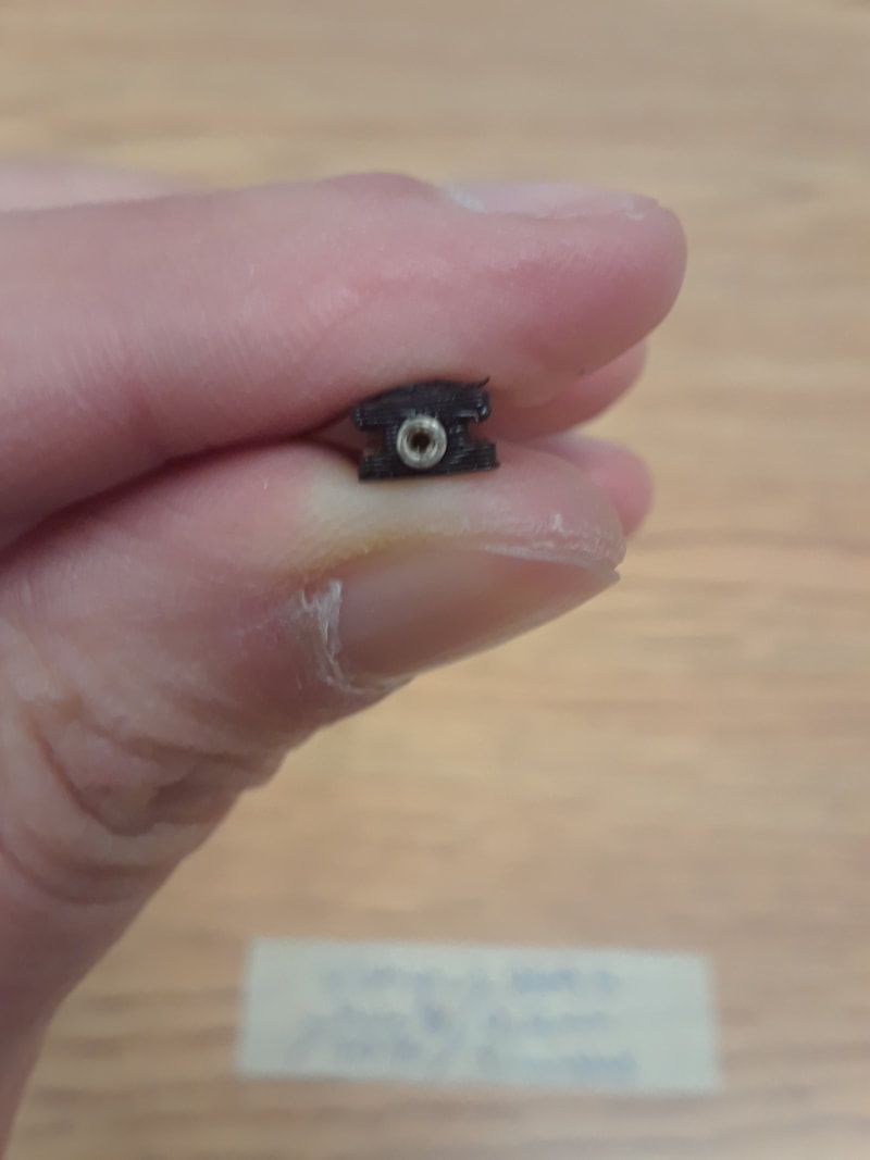
I did a few things. First was the JST connectors arrived, so I figured out where it should go for the strings. I didn't solder them yet though. Second was even more troubleshooting issues with the strips… I spent the past week or so focusing on mechanical issues rather than electrical. I’ve been printing lots of strips because of it, but not testing them. Now I think I have figured out a good relationship between the strips and the fingerboard, so I am testing the resistance again. 4Ebony_DStrip.stl One problem is that superglue insulates the header. Too much glue and I lose the connection. I think I developed a way to get it right, but only after accidentally messing up the D and A strips. I tried soaking them in rubbing alcohol and in nail polish remover, it didn’t help. My solution was to first take a soldering iron and press down on the header for about 5 sec so it would sink deeper into the hole. Then I made a cup of hot water and dipped the end into the cup. After that I squeezed the edges so that the header would be wedged in. I added superglue to the outside in order to provide support to the edges. It doesn’t look pretty, but it works. Then… the above method only worked with the D strip and I ended up ruining all of the headers with superglue anyways... I adjusted the slot placement and chopped off the bottom half of the fingerboard. I also printed a second piece to hold the header ends. This way I am creating the full length of the fingerboard. I had to completely re-do the design of the strips in order for there to be enough room for them at the nut end. Before they were “I” shaped. Now they are shaped more like how my clamps fit together. I also have to print them with supports because the header end is now flat on the build plate and the rest of the strip is in the air. Not the most ideal way to print, but my tests from a long time ago proved that they can't be printed sideways without ruining the rails that keep the strip in place. These pictures are taken before the ebony base was ready. I just placed the prints on for the sake of measuring. Since printing the entire fingerboard was not working, Aaron had an idea to help make it stronger. I print only the top portion of the fingerboard, and he makes an ebony base. This means that the fingerboard will not have the under-curve, but at least it should be strong enough. We'll see how it affects the sound. This was his drawing. 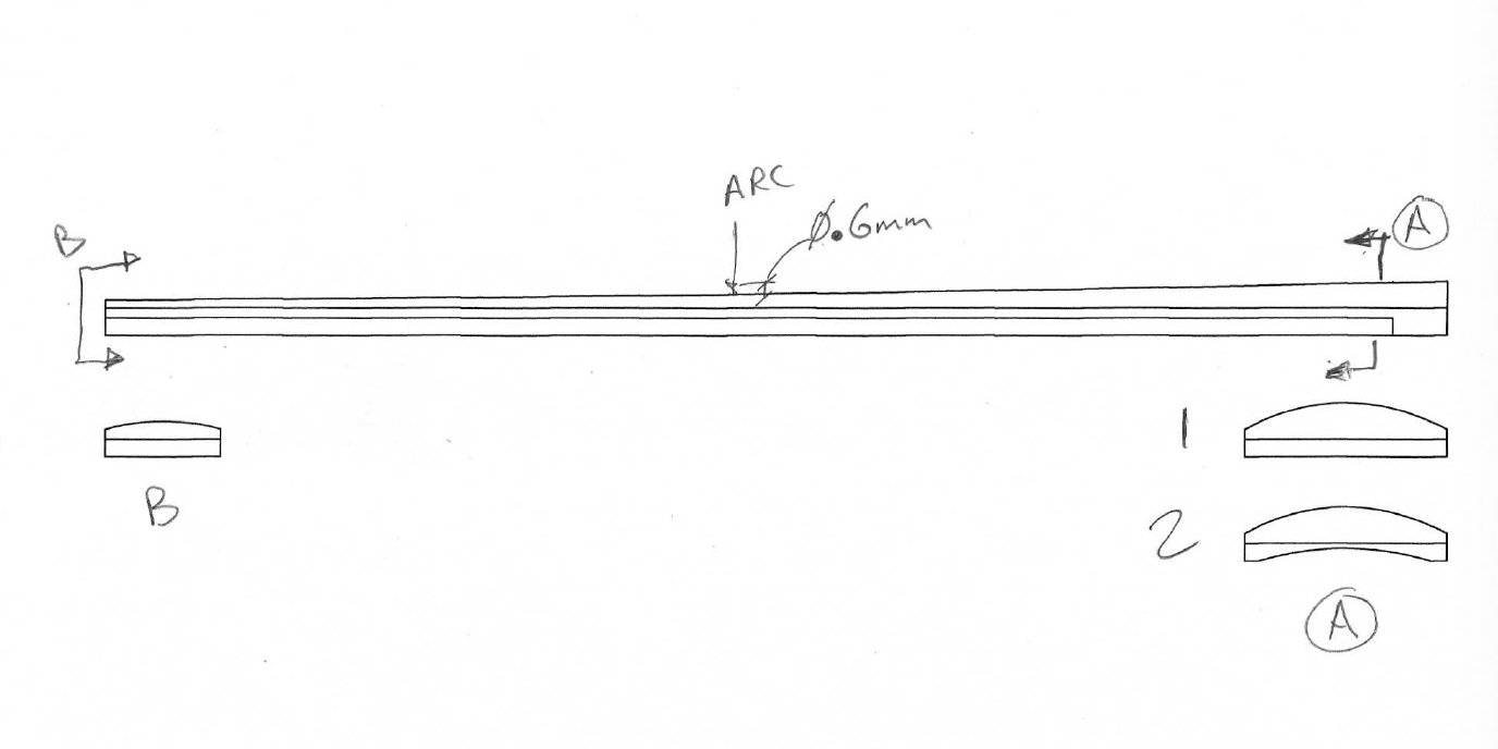 I’ve been printing parts for the Arduino case. The lipo battery I have is slightly smaller than the last one, so I had to make some adjustments to the dimensions of its box. The first time I printed it, it was a little bit too small. But I got it on the second try. There was something interesting I noticed about the clamps that I printed. They were all from the same file, but their lengths were ever so slightly different. I then realized that it must have had to do with which way they were oriented while printing, and gravity was affecting it.
Even though the last fingerboard print wasn’t working, I put it on my violin in order to see how the outer dimensions fit, and how the slots line up under the strings. It was a little too tall on the nut end. The two outer slots should be moved over a bit. However, I discovered an even bigger problem: the fingerboard bends when playing in the high positions.
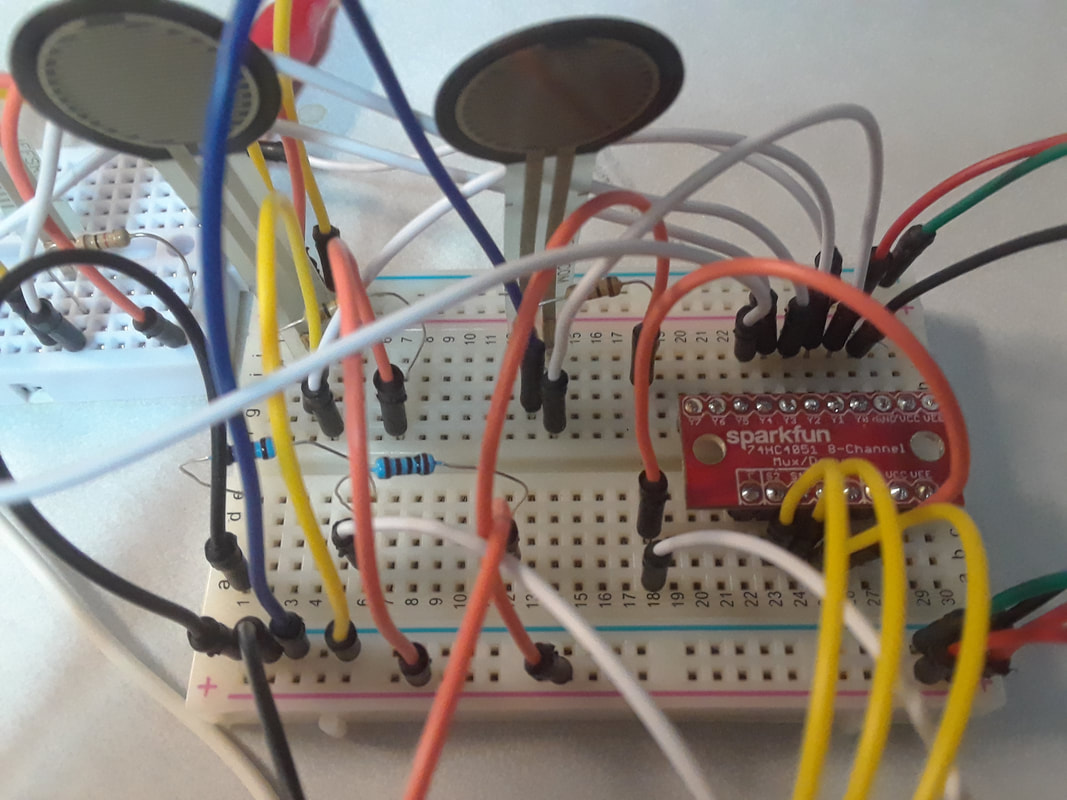
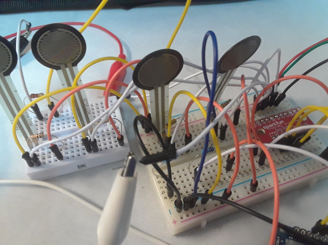
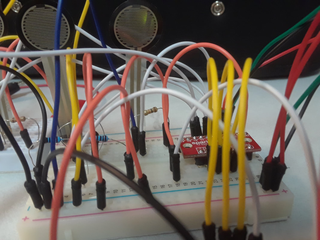
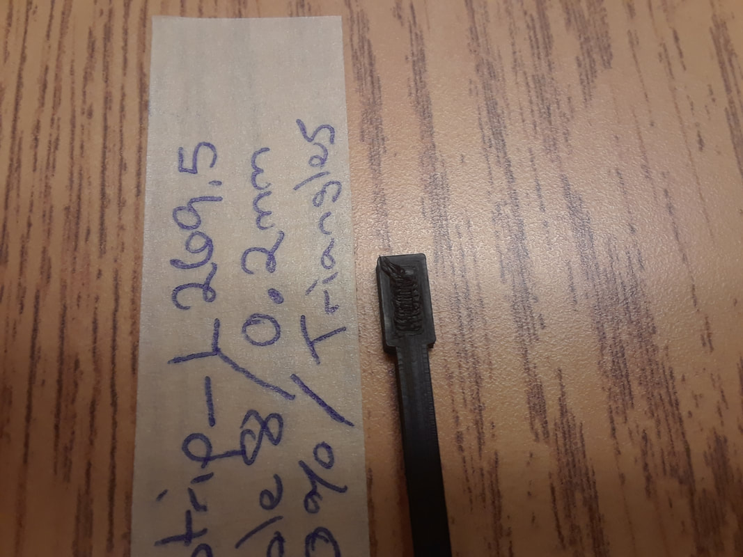
I made the length of the fingerboard slightly shorter in order to accommodate the smaller build plate of the Ultimaker. It curves a bit. Another problem is that 3 out of four strips don’t fit. It kind of looks like a Wolverine claw. I’m not sure why because they were all modelled with the same dimensions. Because of how the model curves on top of the fingerboard, it’s not perfectly smooth. I successfully figured out how to multiplex with the Sparkfun 8 Channel (74HC4051). My long breadboard is half dead, so I had to manage on a couple small ones. Printing the actual fingerboard strips are a bit more of a challenge than the test strips, because the top surface is curved. Layer height 0.1mm, Infill Density 70%, Pattern: Triangles.
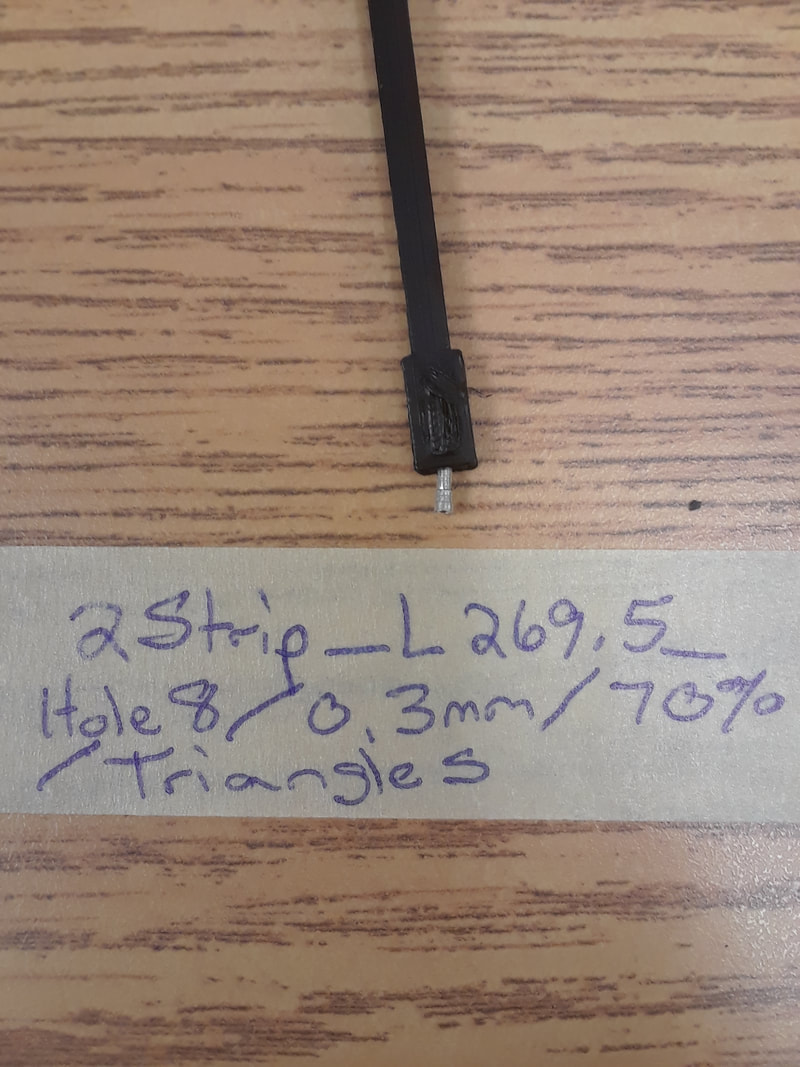
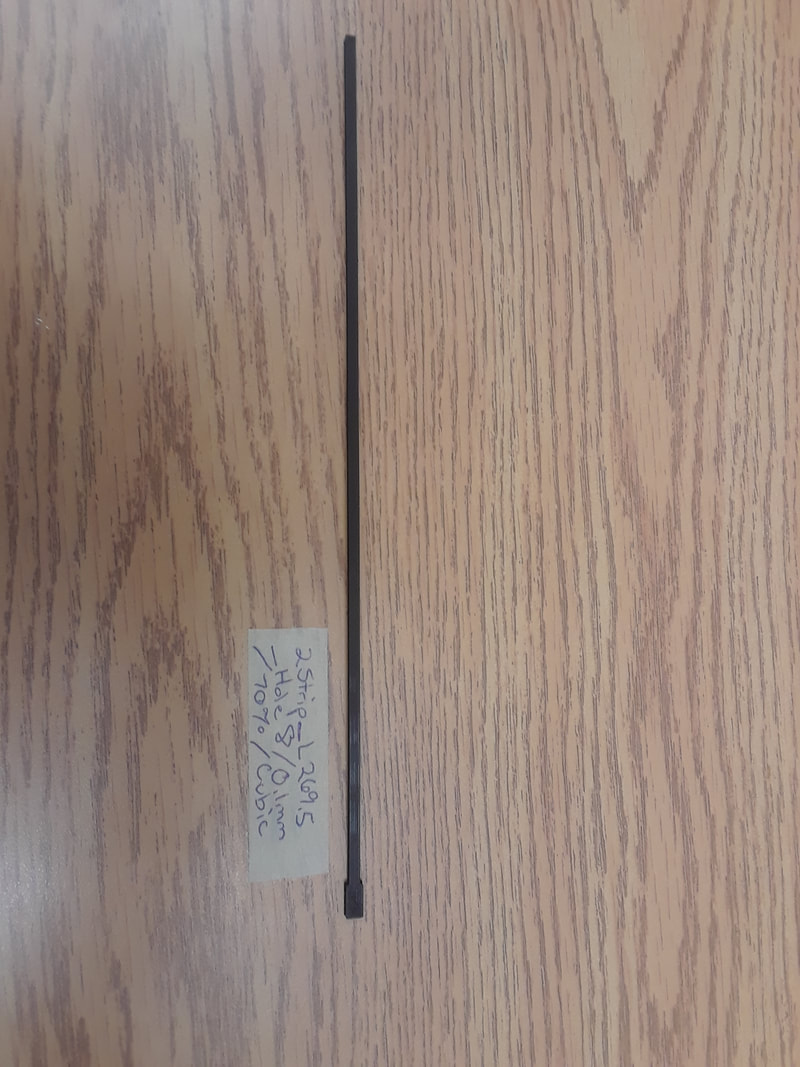
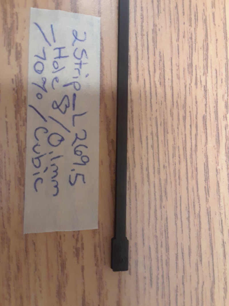
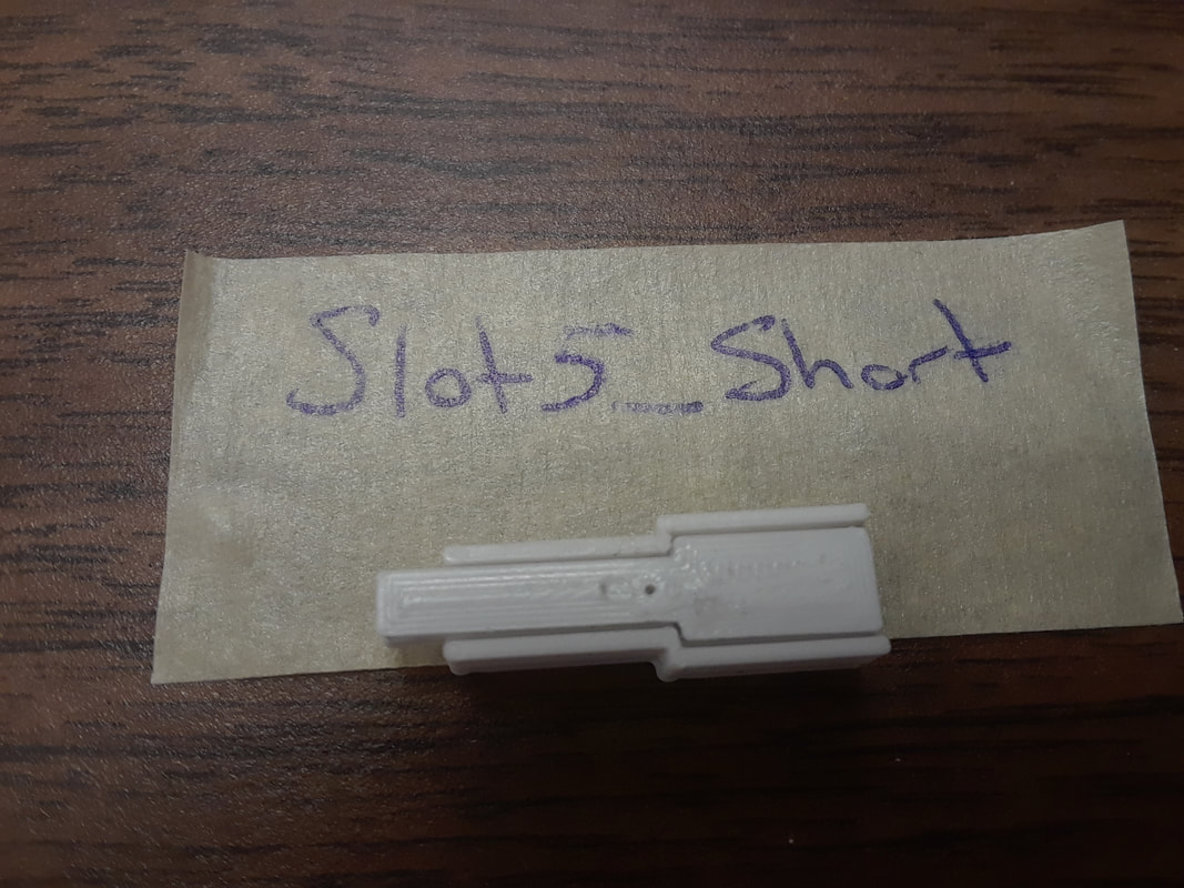
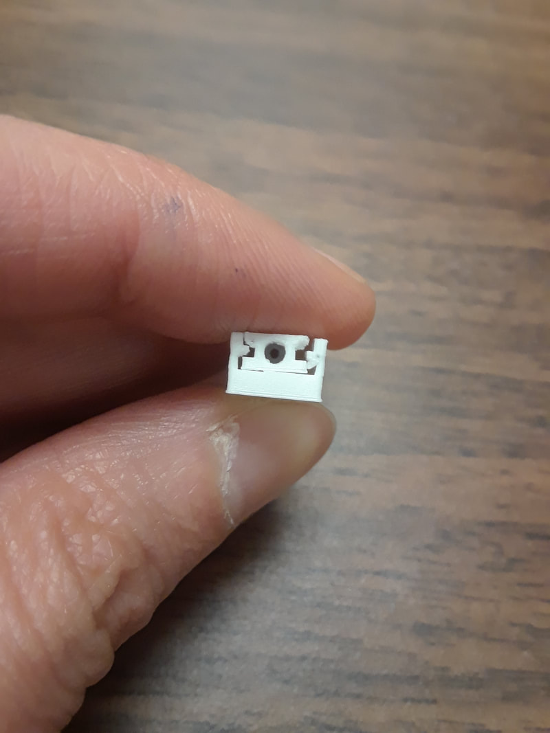
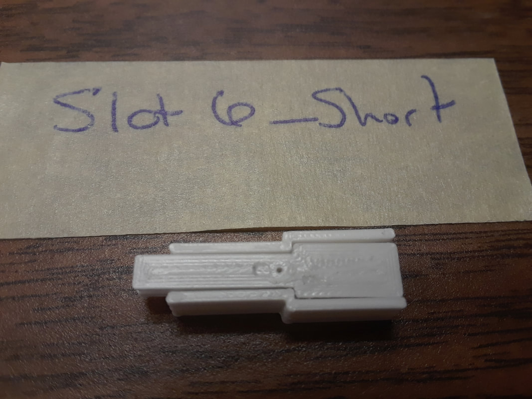
EStrip_Short.stl E strip is on a bit of an angle, so I had to rotate it flat in Cura. The problem is, is that it is difficult to tell if it’s rotated properly or not. There is a bit of overhangs inside the tracks that need to be picked out. It’s also a little on the rough side as it gets closer to the nut end, but not too bad. The header hole is perfect. The resistance fluctuates a lot at the ends. 20MW Close: 0 Mid: 0 End:0 2MW Close: 0.002 Mid: 0.006 End: 0.009 200KW Close: 1.7 Mid: 5.0 End: 8.3 20KW Close: 1.46 Mid: 5.3 End: 9.8 2kW: 0L GStrip_Short.stl Turned out similarly to the E. I think the overhangs are a bit better though. 20MW Close: 0 Mid: 0 End:0 2MW Close: 0.001 Mid: 0.004 End: 0.07 200KW Close: 2.2 Mid: 3.9 End: 6.8 20KW Close: 1.45 Mid: 4.31 End: 6.91 2kW: 0L DStrip_Short.stl This is better than the G and E strips. Probably because the bottom is flatter. It was made with support checked off. 20MW Close: 0 Mid: 0 End:0.01 2MW Close: 0.003 Mid: 0.005 End: 0.009 200KW Close: 3.5 Mid: 5.7 End: 8.7 20KW Close: 1.78 Mid: 5.33 End: 9.25 2kW: 0L AStrip_Short.stl First time I printed, it turned out ok. However, the nut end was peeling off the build plate and it not useable. I’ll try again with it flipped over. The flipped over orientation was fine. I don’t know what went wrong before, because I printed all the other strips this way before. I tested the 2nd print, not the first print. 20MW Close: 0 Mid: 0 End:0 2MW Close: 0.001 Mid: 0.003 End: 0.009 200KW Close: 1.5 Mid: 4.0 End: 8.3 20KW Close: 1.36 Mid: 4.27 End: 8.32 2kW: 0L 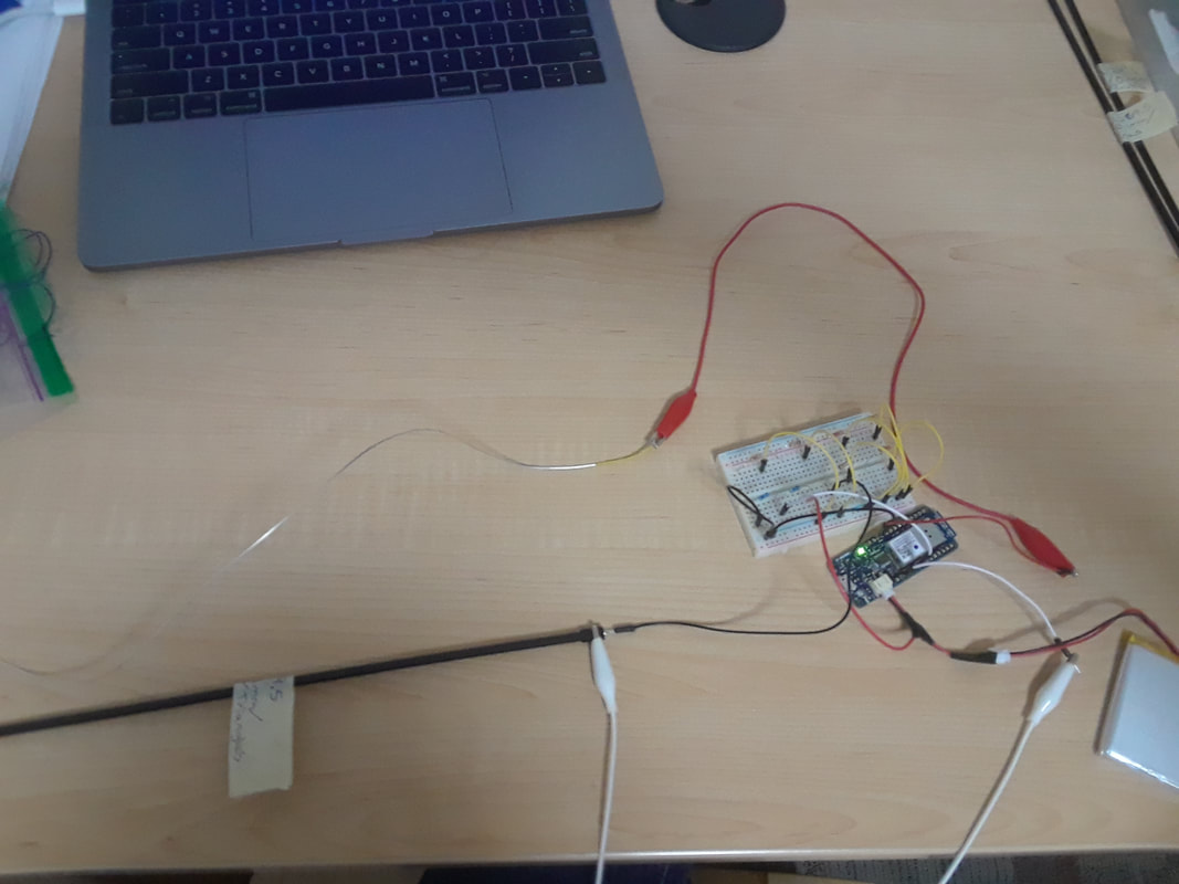 I did a lot of testing with strip file 2Strip_L269.5_Hole8.stl with the Arduino. It was printed with a layer height of 0.1mm and triangle pattern. I compared The Dominant strings and the Evah Pirazzi’s, and combined them with a series of different resistors.
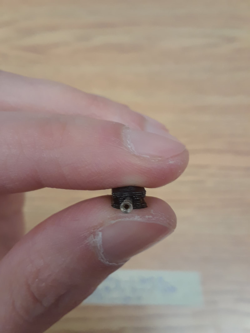
G Dom The voltmeter reading is consistent with the string testing in that everything is much more stable. I am actually estimating more confident readings with this than the last test strip that I tested with the Arduino. none: 20-85 1k: 105-375 3.3k: 260-720 4.7k: 330-750 10k: 510-850 22k: 710-945 47k: 845-975 G Evah none: 20-85 1k; 108-300 3.3k: 255-685 4.7k: 325-700 10k: 500-840 22k: 705-930 47k: 855-1003 D Dom none: 16-70 1k: 105-245 3.3k: 255-645 4.7k: 330-545 10k: 518-805 22k: 705-915 47k: 845-970 D Evah none: 20-105 1k: 110-450 3.3k: 265-640 4.7k: 340-750 10k: 515-840 22k: 715-920 47k: 850-980 A Dom none: 20-50 1k: 108-440 3.3k: 245-630 4.7k: 330-550 10k: 505-840 22k: 705-930 47k: 845-975 A Evah none: 15-50 1k: 95-120 3.3k: 235-490 4.7k: 320-595 10k: 500-740 22k: 685-805 47k: 845-920 E Dom This string fluctuates more than the rest of the strings that come in the dominant pack. 22k must have been a mistake as I was brain dead by the time I got here. none: 15-33 1k: 90-250 3.3k: 215-370 4.7k: 295-550 10k: 380-630 22k: 650-450 47k: 815-885 E Pirastro Gold This one is more stable than the dominant E. none: 18-60 1k: 105-400 3.3k: 250-540 4.7k: 315-765 10k: 500-885 22k: 640-915 47k: 830-985 E Evah none: 15-45 1k: 102-250 3.3k: 205-560 4.7k: 320-660 10k: 480-740 22k; 670-920 47k: 840-940 I also discovered that the printer made hole8 perfect with the regular pla, but when I used the conductive pla, the header didn’t quite fit, so I am testing again with the conductive… L. Files: Hole9.stl, Hole10.stl, Hole9.2.stl.
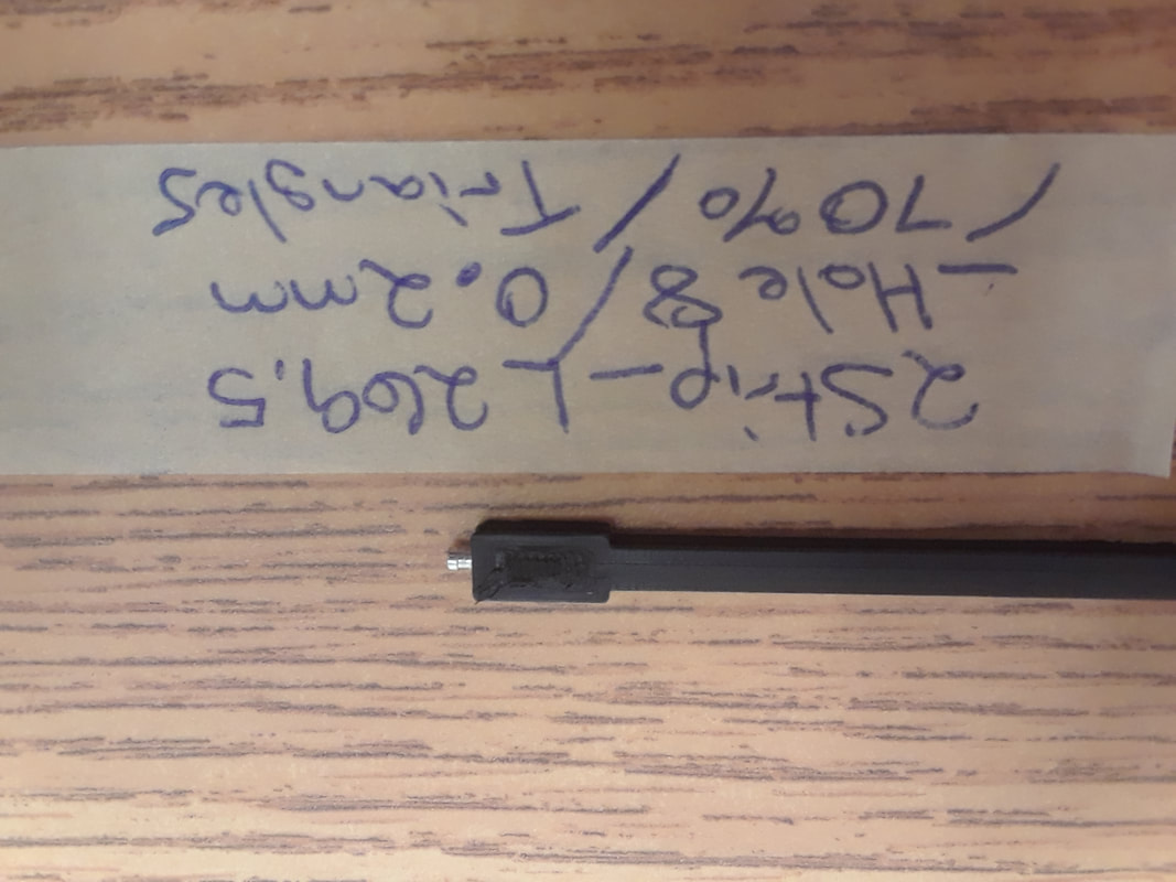
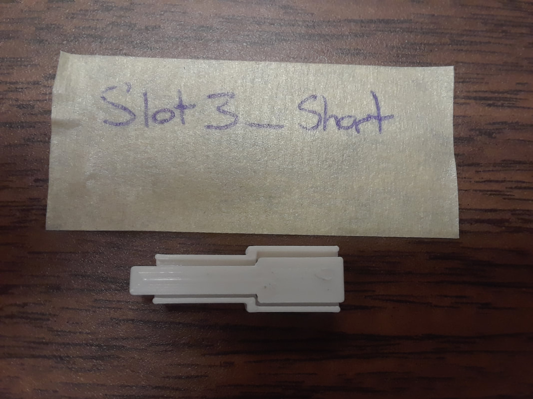
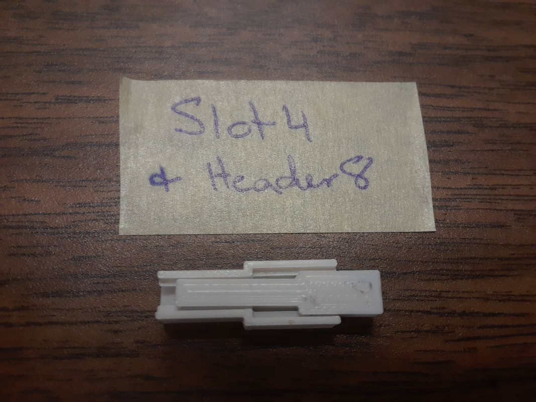
I decided to change up the printer settings to see if that changes the resistance of the same strip file. Infill density was always 70%. I tested different layer height thicknesses and different infill patterns. There was no significant differences with different patterns, but there was with different thicknesses. Test strip file: 2Strip_L269.5_Hole8.stl Strips: Layer Height: 0.1 mm. Infill Pattern: Triangles: Good fit with the test slot7. Good space at the very end to fit the needle. Took 44min to print. The header is not quite fitting in perfectly like it was with the regular PLA. It might have to do with the differences between conductive and regular? It’s not that bad though. I can still work with this. When I tested with the volt meter, the readings are much more stable than the last print that I tested with a volt meter for. When comparing with the other thicknesses, I think the 0.1mm is more stable than the others, but it’s really hard to tell. Multimeter Readings: 20MW : Close: 0 Mid: 0 End: 0.01 2MW : Close: 0.003 Mid: 0.007 End: 0.011 200KW Close: 4.0 Mid: 6.2 End: 11.2 20KW Close: 2.55 Mid: 6.1 End: 11.6 2kW: nothing Layer Height: 0.2mm. Pattern: Triangles. Takes 23 min to print. The top of the header piece is messed up and the header doesn’t fit in the slot. Better than the 0.3 though. Multimeter Readings: 20MW Close: 0 Mid: 0 End: 0 2MW Close: 0.003 Mid: 0.006 End: 0.009 200KW Close: 2.3 Mid: 6 End: 9.8 20KW Close: 3.38 Mid: 6.5 End: 8.66 2kW: 0L Layer Height: 0.3mm. Pattern: Triangles. Takes 16min to print. Much better than the 0.5mm infill. The top of the header piece is messed up and the header doesn’t fit in. This one fluctuates more than the other two. Multimeter Readings 20MW Close: 0 Mid: 0 End: 0 2MW Close: 0.004 Mid: 0.006 End: 0.01 200KW Close: 2.5 Mid: 9.5 End: 0L 20KW Close: 1.27 Mid: 5.8 End: 7.7 2kW: 0L Layer Height: 0.5mm. Pattern: Triangles. Takes 10min to print… don’t know why it’s so much different from the last one. It turned out absolute crap. The header looks messy at the top. I’m not even going to try to fit a header in there. It’s slightly smaller than the edges of slot7, so it is not flush with the top. Harder to get off of the build plate, so the header bent a bit, and won’t bend back. Not functional. Numbers are lower than the thinner thicknesses. The thicker the layer height, the worse the resistance gets. Multimeter Readings: 20MW : Close: 0 Mid: 0 End:0.01 2MW : Close: 0.002 Mid: 0.006 End: 0.02 200KW Close: 3.1 Mid: 4.7 End: 7.0 20KW Close: 1.64 Mid: 4.06 End: 6.82 2kW: 0L I made the test slots short so I could see how they are fitting and not waste filament. I tested the slots with the HeaderHole8.stl file.
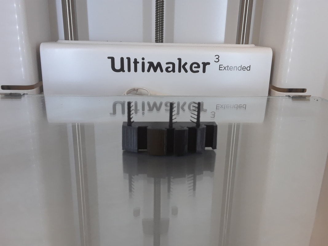
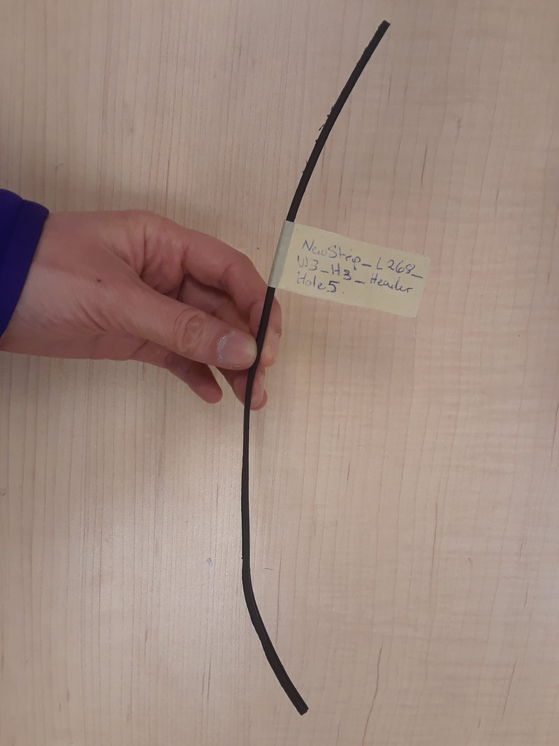
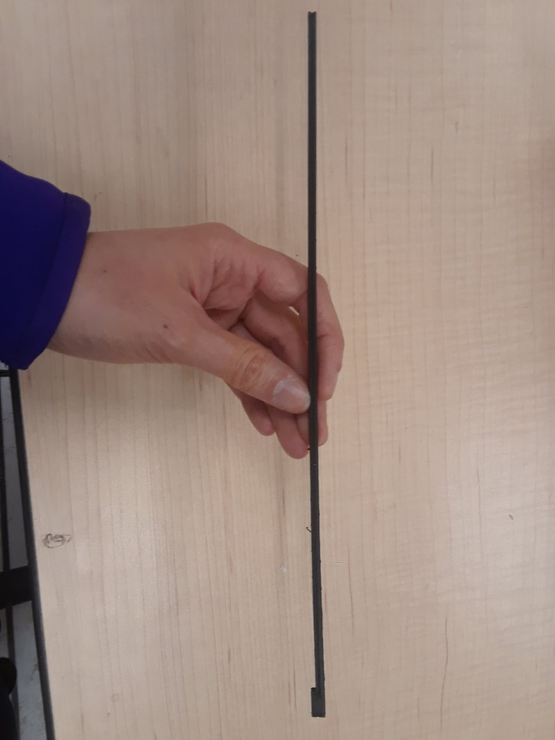
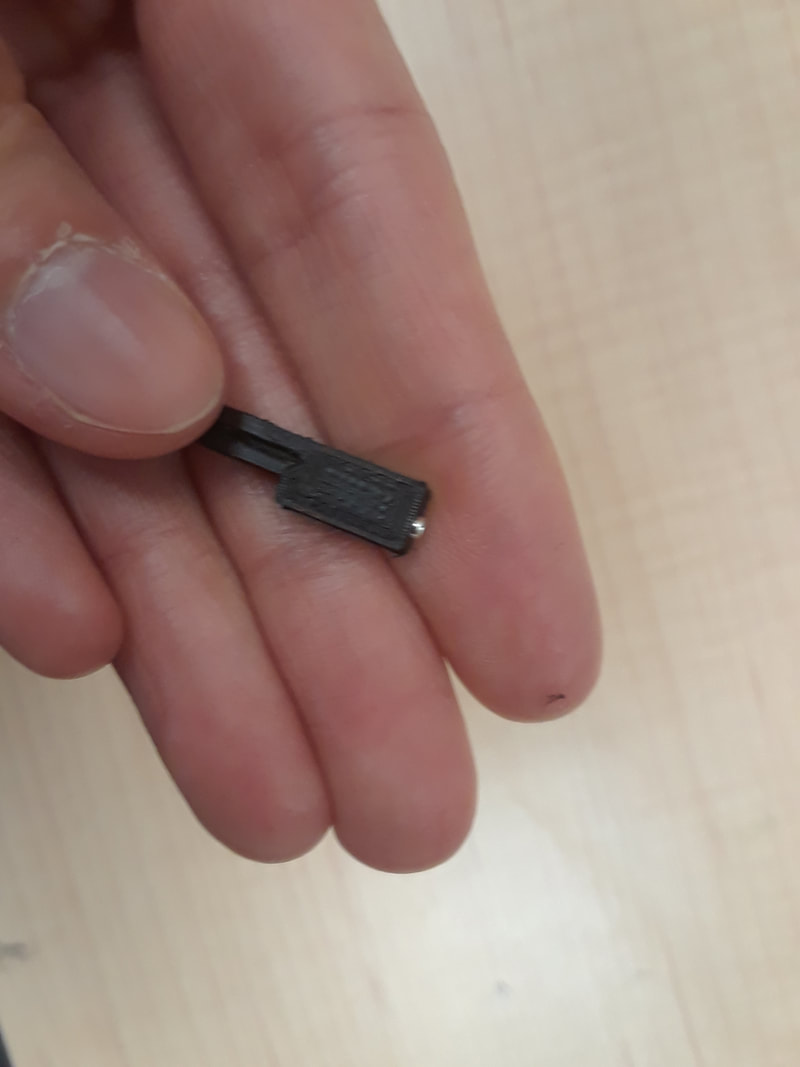
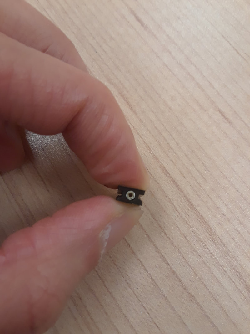
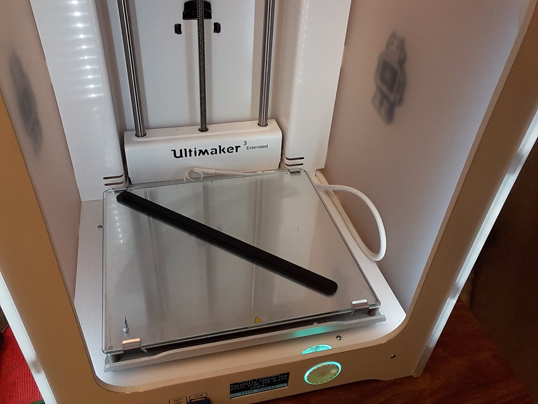
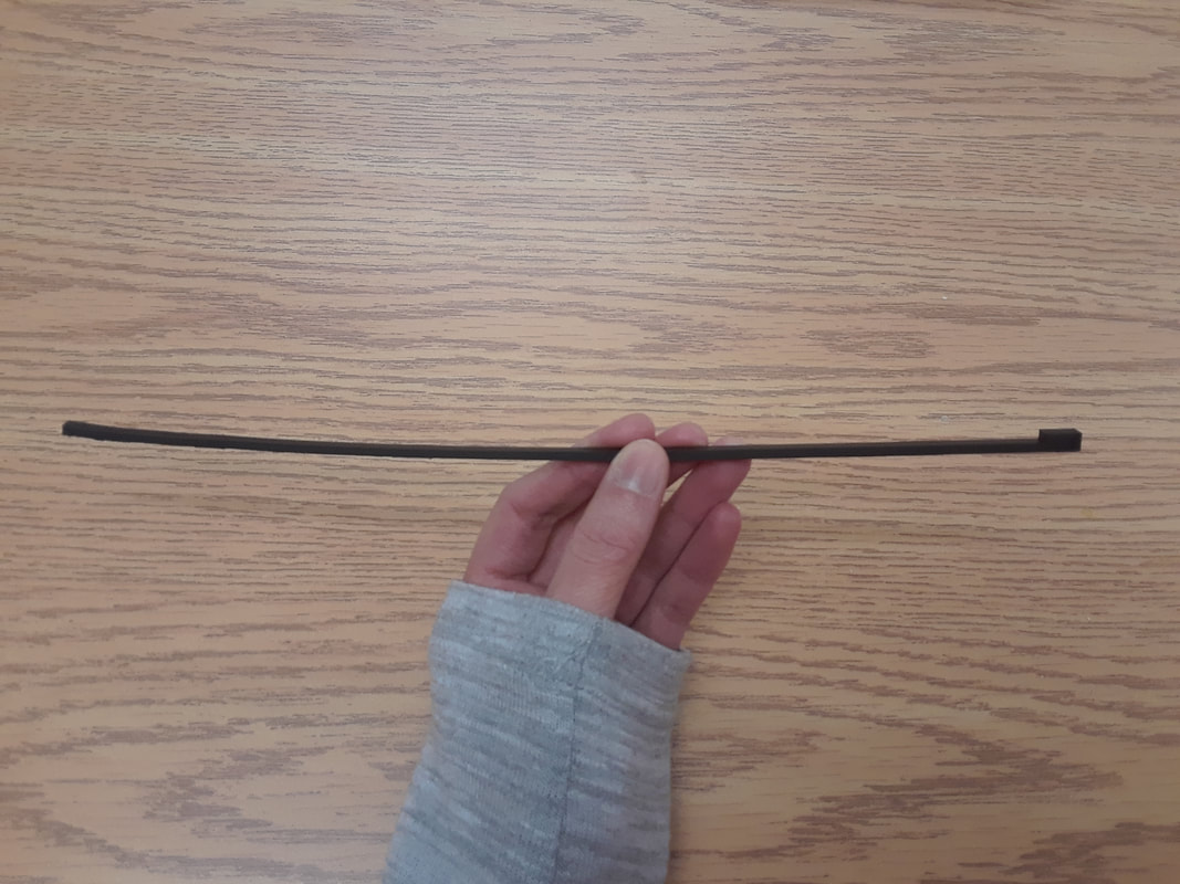
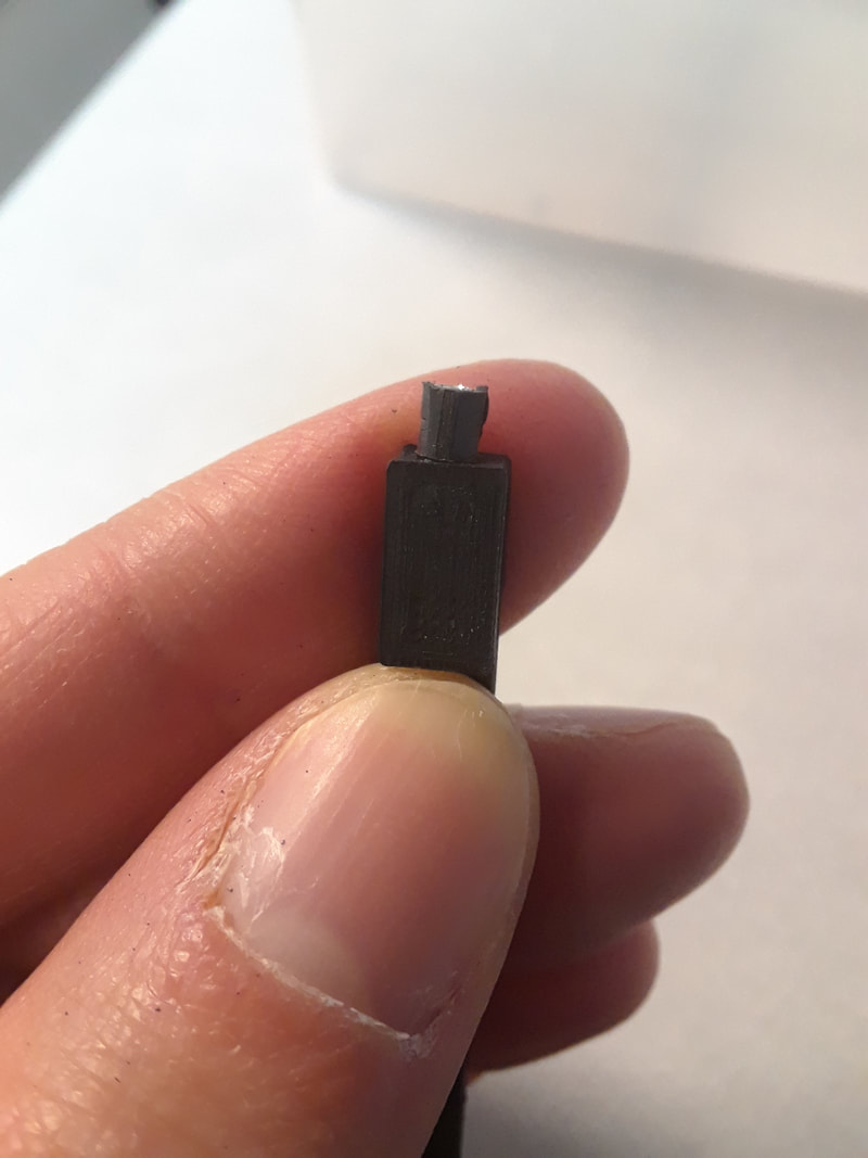
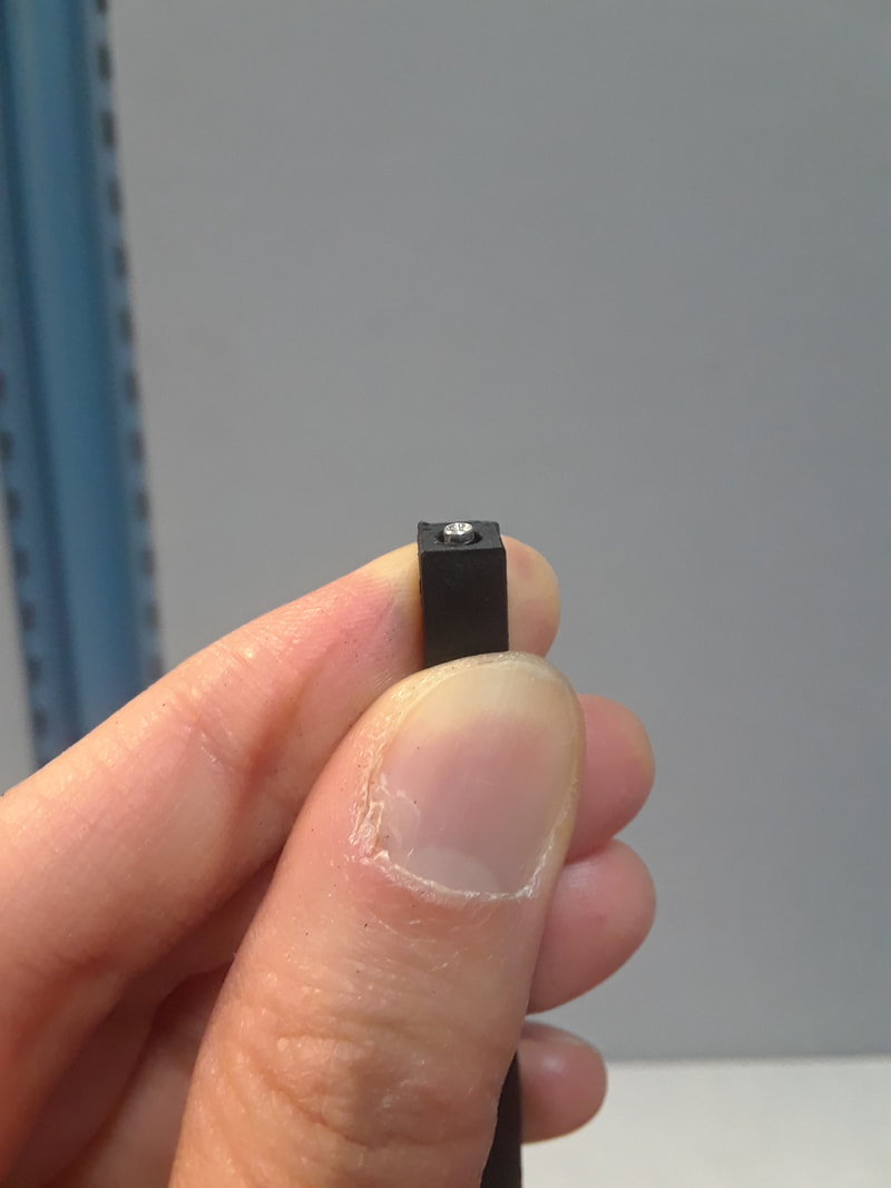
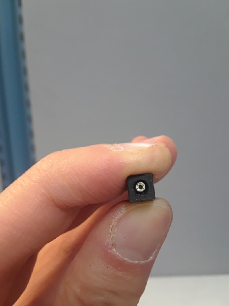
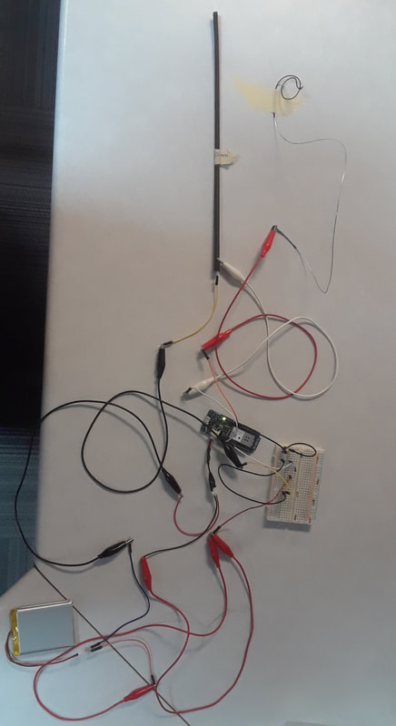
Files printed: NewStrip_L268_W3_H3_HeaderHole5.stl, NewStrip_L268_W3_H3_HeaderHole6.stl, NewStrip_L268_W3_H3_HeaderHole7.stl, and HeaderHole8.stl. I discovered a few things about printing these very long, thin strips. When I modeled “…5” I added two holes on either side so the strip can slide into the fingerboard and be held there. “rails” I call them. I turned this print on its side so that it was laying on one of its rail sides. I also included half of a header hole for the next testing of that. I wanted to use dual extrusion with the second extruder printing the raft in PVA. However, when I selected raft instead of brim, the parameters of the build plate became smaller and way too small for the model. So I’m just going to stick with brim with support for now; all using single extrusion. When I pulled the print off, it curled way more than the last print. The rails also got stuck to the brim and I ripped some of them right off. It is damaged beyond usability, so I’m not going to test this one with the Arduino. When I tested it with the header, I did it in two extrusions. The first hole was a bit too small in diameter, and a bit too long in length. The second hole was a bit too big in diameter, and a bit too long too. When I modeled “…6”, the strip stayed the same, but the header hole changed a bit. I tried printing it flat (not on top of the rails), without a brim, and no supports. This time it stayed much firmer and didn’t bend so much. This time it stayed much firmer and didn’t bend so much. However, I accidentally snapped it at the end when I tried to take it off the plate. Going to see if I can print it on it’s side again because printing it flat this way will cause a problem later on. I’m not going to test this with the Arduino because it’s broken. For the hole, the first hole needs to be a bit bigger in diameter, and it’s just right in length. The second hole looks like the right diameter, but needs to be slightly shorter. When I modeled “…7” I printed it on it’s side again (rail side). I think I developed a technique to scrape it off the build plate with minimal damage to the print: by starting in the middle and scraping along the edges. By having the side that is exposed to the fingers, on the side instead of up, it caused periodic bumps along the surface. This is problematic. I will have to see if I can sand it down, or for the next print, print it on it’s other end, with supports. The only other way I can think of is make the bit around the header wider, don’t make it reach all the way down, and have a wider set of rails on the header piece. That way the whole thing is flat… maybe that is a better solution actually. I’ll test it with the Arduino another day because it’s getting late right now. For the hole, I didn’t account for the outer rim of the header being wider. That’s why it’s not fitting quite right. Otherwise it’s perfect and snug. Next time I print a hole, I’ll made it three extrusions again, 1 for the rim, the other for the body, the last for the pin. HeaderHole8: I left a little bit of the strip to see how it would look. I did the solution above, with making it a bit wider around the header hole than the rest of the strips, and add rails to it. The hole is a snug fit!!!!!! Now for testing the new strip with a “mock-up” fingerboard to test if the rails fit... Happy birthday to me! File name: HalfHeaderHole2 I only got one print done before the nozzle clogged. I was trying to figure out the size of the header hole by printing just that one piece. Instead of printing the whole piece, I printed half of the diameter, so that way I can clearly see how it’s fitting from the outside. I did it with three extrusions to make the hole. I can now tell that the last extrusion is too narrow. The middle extrusion looks like the right diameter. The first extrusion is way too wide if the pin is without the casing. I accidentally scratched the print across the last hole in this picture. 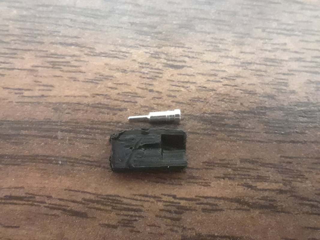 Long story short, THIS WHOLE 3D CONDUCTIVE FILAMENT THING WORKS!!!!!! File printed: Strip2_265mm.stl I made several charts outlining the details for each strip and each possibility with the strings. Maybe when I’m done filling them out I’ll transfer them over to google drive so I can access them online. For now, I’m mostly just reporting on the main points in my blog posts. When I printed my first I found out that it was two milimeters too long. So instead of printing it at 270mm long, it’s 265mm. It was printed with a brim instead of a raft, I thought raft was selected, but it wasn’t so that was my mistake. It stayed flat on the build plate, but when I tried to scrape it off, it was super duper stuck. Getting it off made it bend a bit at the edges. For next time, make sure that the side that is exposed to the fingers is not on the build plate, so that way it is the texture I like. The full fingerboard definitely won’t fit on this printer because of the edges. Also, what might help is make little cylinder extrusions that fit into deeper holes in the fingerboard. May need to make the thickness of the strip even thinner. After printing I tested different sizes of the strip in Cura. The longest that could fit from corner to corner was 268mm. I don’t think those 2 extra mm on length would affect the resistance that much. When I tested with the volt meter, the numbers tend to start high when I first place the prongs on, they jump around for a bit, and then they settle back down. There were two settings where I could get a reading from the volt meter: 200K: Somewhere between 12.something to 22.something. It was just constantly fluctuating. (100,000 x 12 = 1,200,000 – 2,200,000 ) 20K: End: fluctuates between 8-16 Mid: 4-6 Close: 2-4 (10,000 x 2 = 20,000 – 160,000) When I tested with the Arduino I liked having both the data and ground connected to the strip, the resistor connected between the strip and ground, and power connected to the string. I am getting both a change in pressure and linear data. It also works if I connect the alligator clip to the ball of the string… a little something to think about when I am in the final stages of hooking up. When the sensor is at rest, it jitters like the softpots do. Everything is jitter-y no matter which resistor I include in the circuit too. I forgot to solder an extra wire coming out of the power in order to hook up the battery to the resistors, so that’s why there are a multitude of wires going on around the battery haha. Since everything is so jittery use peak => [if $i1 > y then $i1 else y] => [scale x y 0. 1023.] Also the jitter at rest solution that I came up with before. Conclusions with this particular strip: G Evah has a larger range than G Dom. D Evah has a larger range than D Dom. A Dom has a larger range than A Evah. => they are both made from Aluminum. What is it about their winding that makes one so much better than the other? E Pirastro Gold has a larger range than E Evah. More consistency in resistors from the Evah Pirazzi Pack as a whole. If I chose Dominants, if 3.3k is not the first choice of resistor it is at least the second choice. Pirastro Gold E is the best with a 3.3k is the best. As for the header hole I decided to print this with my first approximation. If I kept the black casing around the swiss machine head, then the hole was too small in diameter. But I found the black casing to be peeling off anyways, so I picked it off. Without the casing, it fits, but the hole is slightly too short in length. And the largest part of the hole is a bit too large in diameter. |
Welcome to the TRAVIS blog!If you would like to see a summary of my work, please click here. Archives
May 2022
Categories


|


 RSS Feed
