CHANTELLE KO
  • Home
  • Bio
  • GLOBE
    • GLOBE Videos
    • GLOBE Gallery
    • Sensational World of Sensors
    • GLOBE Blog
  • TRAVIS
    • TRAVIS Videos
    • TRAVIS Blog
  • SUBCLASS
  • Other Academia
    • Soundscapes
    • Augmented Props
    • Sofra Ensemble
    • Music Tech Works
  • Resources
  • Contact

Printer Settings and Holes

22/2/2019

0 Comments

 
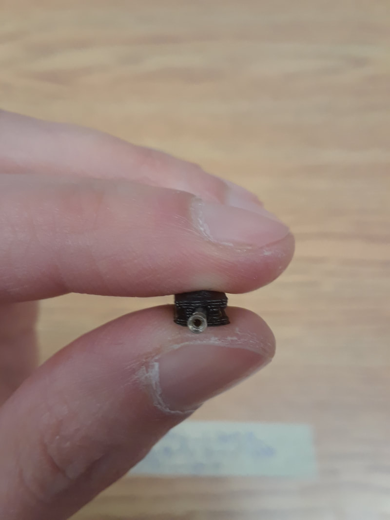
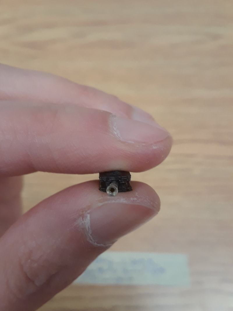
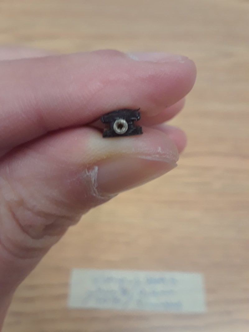
I also discovered that the printer made hole8 perfect with the regular pla, but when I used the conductive pla, the header didn’t quite fit, so I am testing again with the conductive… L.
Files: Hole9.stl, Hole10.stl, Hole9.2.stl.  
​
  • Hole9: I think it got sliced weird with it being short. I don’t know, but it was even worse.
  • Hole10: It fits nicely, but also pops out a bit too easily. Hole9 might just needs to be re-printed with the fixed extrusion. I’ll try that again.  
  • Second time printing Hole 9: Should use a bit of glue around the edges. I printed this with strip_L268.5_Hole9. Once again it didn’t quite fit. This is annoying me. When I print the strips for real I will try the second extrusion with a diameter of 2mm. If that still does not work, then try 2.1mm. But when I tried Hole10 2.2mm was too big.

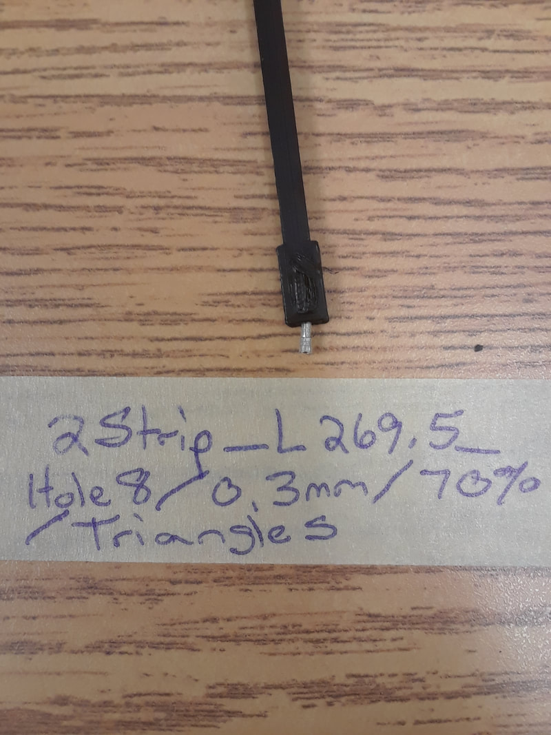
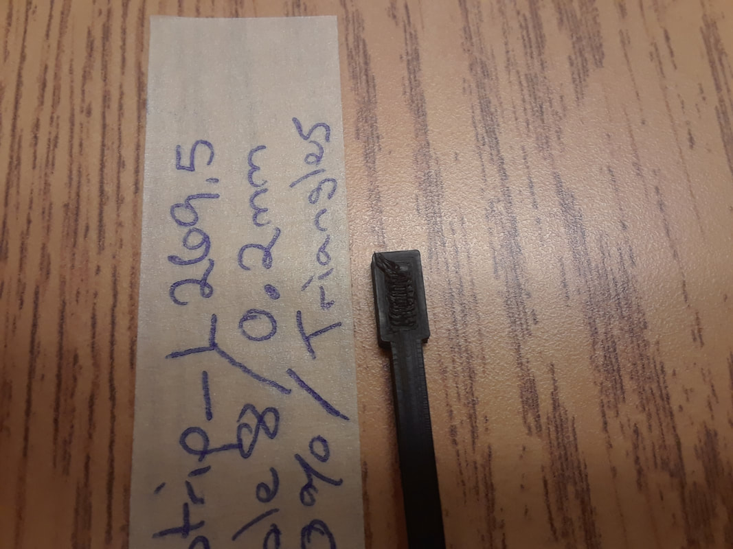
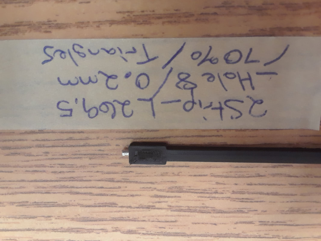
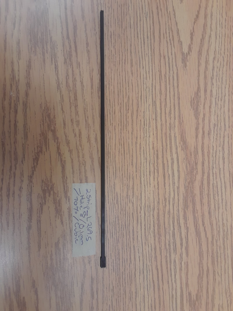
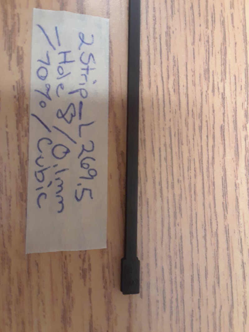
I decided to change up the printer settings to see if that changes the resistance of the same strip file. Infill density was always 70%. I tested different layer height thicknesses and different infill patterns. There was no significant differences with different patterns, but there was with different thicknesses.
Test strip file: 2Strip_L269.5_Hole8.stl 
 
Strips:
Layer Height: 0.1 mm. Infill Pattern: Triangles:

Good fit with the test slot7. Good space at the very end to fit the needle. Took 44min to print. The header is not quite fitting in perfectly like it was with the regular PLA. It might have to do with the differences between conductive and regular? It’s not that bad though. I can still work with this. 
 
When I tested with the volt meter, the readings are much more stable than the last print that I tested with a volt meter for.
 
When comparing with the other thicknesses, I think the 0.1mm is more stable than the others, but it’s really hard to tell.
 
Multimeter Readings:
20MW :
Close: 0
Mid: 0
End: 0.01

2MW :
Close: 0.003
Mid: 0.007
End: 0.011

200KW 
Close: 4.0
Mid: 6.2
End: 11.2

20KW
Close: 2.55
Mid: 6.1
End: 11.6

2kW: nothing

Layer Height: 0.2mm. Pattern: Triangles.
Takes 23 min to print. The top of the header piece is messed up and the header doesn’t fit in the slot. Better than the 0.3 though.
Multimeter Readings:
20MW  
Close: 0
Mid: 0
End: 0

2MW  
Close: 0.003
Mid: 0.006
End: 0.009

200KW 
Close: 2.3
Mid: 6
End:  9.8

20KW
Close: 3.38
Mid: 6.5
End: 8.66

2kW: 0L

 
Layer Height: 0.3mm. Pattern: Triangles.
Takes 16min to print. Much better than the 0.5mm infill. The top of the header piece is messed up and the header doesn’t fit in. This one fluctuates more than the other two.
 
Multimeter Readings
20MW
Close: 0
Mid: 0
End: 0

2MW
Close: 0.004
Mid: 0.006
End: 0.01

200KW 
Close: 2.5
Mid: 9.5
End:  0L

20KW
Close: 1.27
Mid: 5.8
End: 7.7

2kW: 0L

 
Layer Height: 0.5mm. Pattern: Triangles.
Takes 10min to print… don’t know why it’s so much different from the last one. It turned out absolute crap. The header looks messy at the top. I’m not even going to try to fit a header in there. It’s slightly smaller than the edges of slot7, so it is not flush with the top. Harder to get off of the build plate, so the header bent a bit, and won’t bend back. Not functional.
Numbers are lower than the thinner thicknesses. The thicker the layer height, the worse the resistance gets.
 
Multimeter Readings:
20MW :
Close: 0
Mid: 0
End:0.01

2MW :
Close: 0.002
Mid: 0.006
End: 0.02

200KW 
Close: 3.1
Mid: 4.7
End: 7.0

20KW
Close: 1.64
Mid: 4.06
End: 6.82

2kW: 0L 

0 Comments


Leave a Reply.

    Welcome to the TRAVIS blog!

    ​If you would like to see a summary of my work, please click here.  

    This blog is where I post updates on TRAVIS I & II as I continue developing them.
    TRAVIS I is an augmented violin that uses two Softpot sensors on the fingerboard to control sound fx, and two FSR's to bang presets.
    ​
    My wired prototype, uses an Arduino Lilypad USB. It was made by myself, and under the supervision of Dr. Bob Pritchard. 

    The wireless version uses an Arduino MKR1000. There was a group of engineering students who collaborated with SUBCLASS. Their names are Jin Han, Esther Mutinda, Carol Fu, and Lily Shao. For their own capstone they are utilized the same MKR1000 for the RUBS (Responsive User Bodysuit).  They named their capstone, WiRED (Wireless RUBS Environment Development). I have been modifying their work for my own purposes, as well as collaborating by making pieces with RUBS. 
    Bob Pritchard continues the RUBS project with TASTE. 

    TRAVIS II is was made in collaboration with Lora Oehlberg and luthier, Aaron Pratte. 

    It has four touch sensors​ made from conductive 3D print PLA and a voltage running down the strings. It also has four round FSRs clamped to the body. 

    You can find a videos and performances here. 

    A summary of my wifi connection troubleshooting can be found here. 

    Archives

    May 2022
    July 2021
    August 2020
    May 2020
    April 2020
    February 2020
    December 2019
    October 2019
    August 2019
    April 2019
    March 2019
    February 2019
    January 2019
    November 2018
    October 2018
    August 2018
    July 2018
    May 2018
    April 2018
    March 2018
    February 2018
    January 2018
    December 2017
    November 2017
    October 2017

    Categories

    All

    RSS Feed

    Picture
    Picture
    Picture
Powered by Create your own unique website with customizable templates.
  • Home
  • Bio
  • GLOBE
    • GLOBE Videos
    • GLOBE Gallery
    • Sensational World of Sensors
    • GLOBE Blog
  • TRAVIS
    • TRAVIS Videos
    • TRAVIS Blog
  • SUBCLASS
  • Other Academia
    • Soundscapes
    • Augmented Props
    • Sofra Ensemble
    • Music Tech Works
  • Resources
  • Contact