|
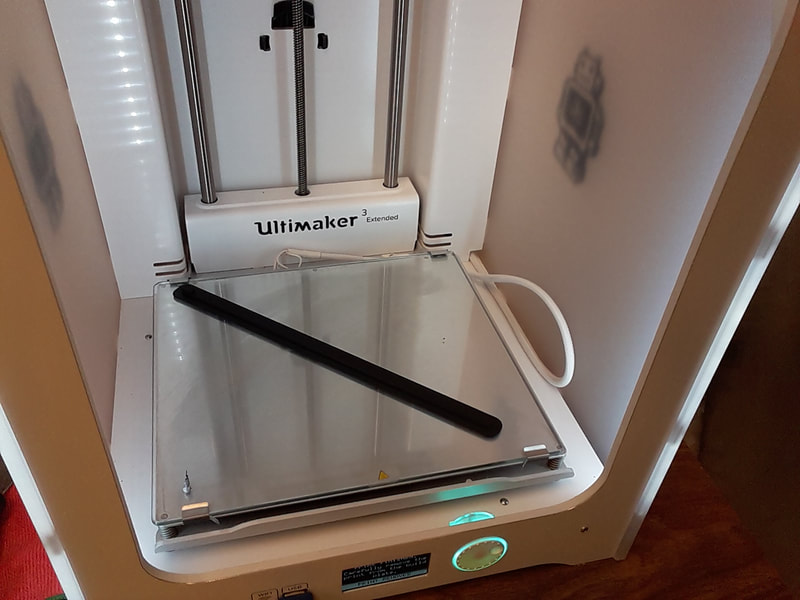
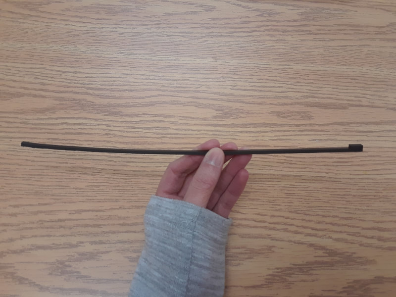
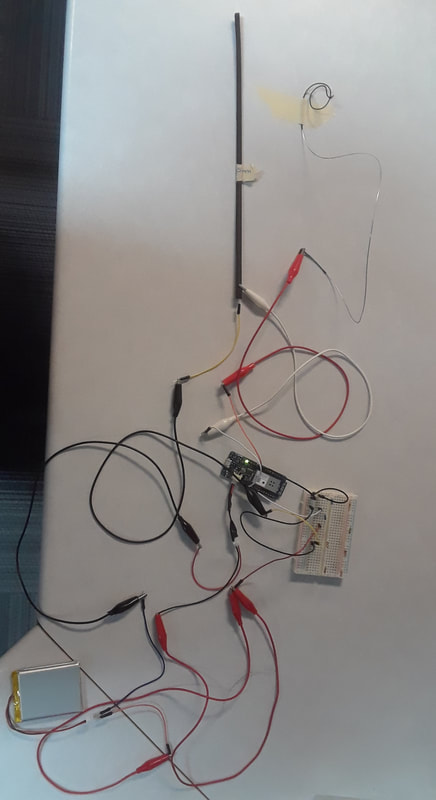
Long story short, THIS WHOLE 3D CONDUCTIVE FILAMENT THING WORKS!!!!!! File printed: Strip2_265mm.stl I made several charts outlining the details for each strip and each possibility with the strings. Maybe when I’m done filling them out I’ll transfer them over to google drive so I can access them online. For now, I’m mostly just reporting on the main points in my blog posts. When I printed my first I found out that it was two milimeters too long. So instead of printing it at 270mm long, it’s 265mm. It was printed with a brim instead of a raft, I thought raft was selected, but it wasn’t so that was my mistake. It stayed flat on the build plate, but when I tried to scrape it off, it was super duper stuck. Getting it off made it bend a bit at the edges. For next time, make sure that the side that is exposed to the fingers is not on the build plate, so that way it is the texture I like. The full fingerboard definitely won’t fit on this printer because of the edges. Also, what might help is make little cylinder extrusions that fit into deeper holes in the fingerboard. May need to make the thickness of the strip even thinner. After printing I tested different sizes of the strip in Cura. The longest that could fit from corner to corner was 268mm. I don’t think those 2 extra mm on length would affect the resistance that much. When I tested with the volt meter, the numbers tend to start high when I first place the prongs on, they jump around for a bit, and then they settle back down. There were two settings where I could get a reading from the volt meter: 200K: Somewhere between 12.something to 22.something. It was just constantly fluctuating. (100,000 x 12 = 1,200,000 – 2,200,000 ) 20K: End: fluctuates between 8-16 Mid: 4-6 Close: 2-4 (10,000 x 2 = 20,000 – 160,000) When I tested with the Arduino I liked having both the data and ground connected to the strip, the resistor connected between the strip and ground, and power connected to the string. I am getting both a change in pressure and linear data. It also works if I connect the alligator clip to the ball of the string… a little something to think about when I am in the final stages of hooking up. When the sensor is at rest, it jitters like the softpots do. Everything is jitter-y no matter which resistor I include in the circuit too. I forgot to solder an extra wire coming out of the power in order to hook up the battery to the resistors, so that’s why there are a multitude of wires going on around the battery haha. Since everything is so jittery use peak => [if $i1 > y then $i1 else y] => [scale x y 0. 1023.] Also the jitter at rest solution that I came up with before. Conclusions with this particular strip: G Evah has a larger range than G Dom.
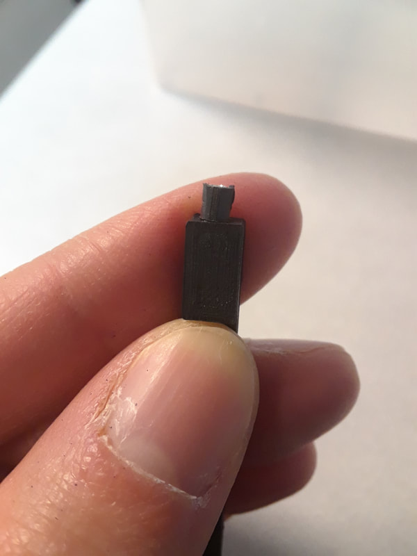
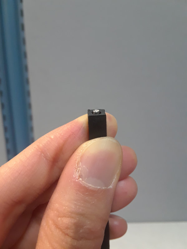
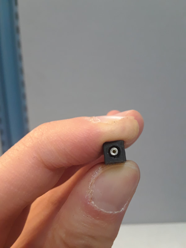
D Evah has a larger range than D Dom. A Dom has a larger range than A Evah. => they are both made from Aluminum. What is it about their winding that makes one so much better than the other? E Pirastro Gold has a larger range than E Evah. More consistency in resistors from the Evah Pirazzi Pack as a whole. If I chose Dominants, if 3.3k is not the first choice of resistor it is at least the second choice. Pirastro Gold E is the best with a 3.3k is the best. As for the header hole I decided to print this with my first approximation. If I kept the black casing around the swiss machine head, then the hole was too small in diameter. But I found the black casing to be peeling off anyways, so I picked it off. Without the casing, it fits, but the hole is slightly too short in length. And the largest part of the hole is a bit too large in diameter.
0 Comments
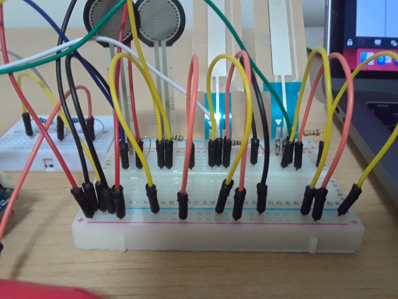
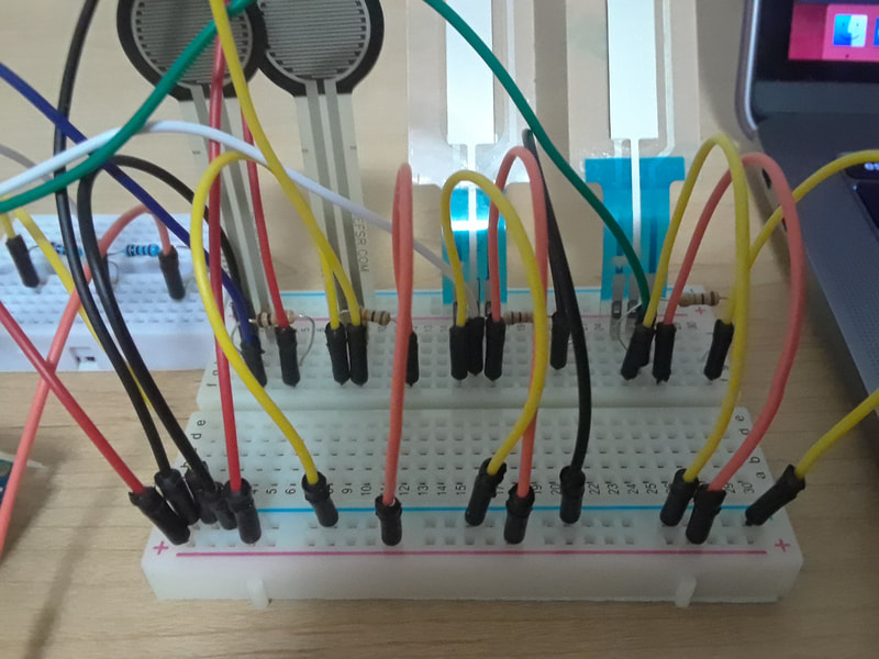
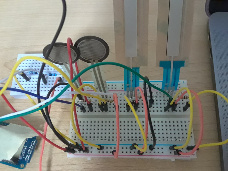
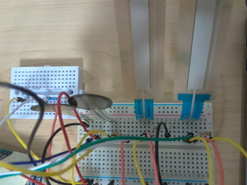
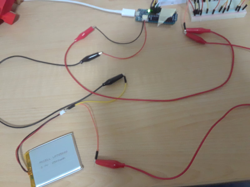
I found out that I had two problems. One was that approximately half of my long breadboard is not working properly, so I had to squish my sensors onto a smaller breadboard that I am borrowing. My other problem was that if the headers on my arduino are perfectly straight, then they are actually not touching the connections on the board. I don't want to solder them down because that would create problems when I want to eventually attach the shield later on. So I used taped to pull them together and so the headers are leaning into the connections on the board. (I can hear the engineers grumbling at my outside of the box solution...)
Anyways... I've been slowly collecting all the parts I expect to need in order to start my TRAVIS II research. Before I get going on that I thought I should re-create my TRAVIS I setup to test out the softpots. Recap on why:
|
Welcome to the TRAVIS blog!If you would like to see a summary of my work, please click here. Archives
May 2022
Categories |


 RSS Feed


