|
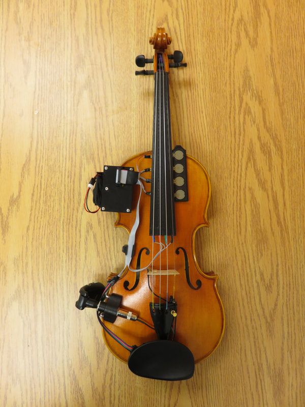
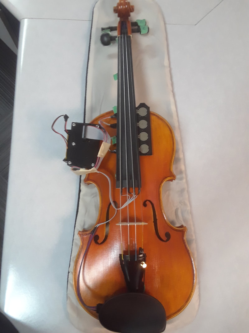
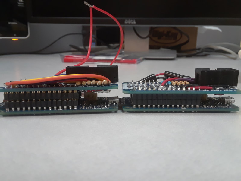
A question that I've been asked is how much additional weight does the electronics put on to the violin. I didn't have a definitive answer before because I didn't have anything the could weigh something that small. But now my fiance and I bought a cooking scale and I weighed the arduino, cases, and batteries with it.
TRAVIS I Arduino + Battery = 112 grams TRAVIS II Arduino + Battery = 129 grams
0 Comments
Mine and Lora Oehlberg's journal article has now been published in the Computer Music Journal. Here is the citation:
Ko, C., & Oehlberg, L. (2021, July) Construction and Performance Applications of an Augmented Violin: TRAVIS II. Computer Music Journal 2021; Vol 44 (2-3), pp. 55–68. https://doi.org/10.1162/comj_a_00563 I was contacted by the NIME paper chairs and my paper was selected to publish an extended version of it in a special issue of the Computer Music Journal by MIT Press! Just when I thought I finished my thesis and was taking a break from academia, another opportunity presents itself!
https://www.mitpressjournals.org/
Today I performed an improvisation in Ned Rush's online micro festival for charity.
I re-uploaded my performance to my youtube channel.
My paper that explains how I made TRAVIS II has been accepted to the NIME conference!!!!!! :)
Due to COVID-19, it's going to be online. I guess I'll decorate my walls with pictures of Britain and pretend I'm travelling this summer :( When I was playing TRAVIS II a couple weeks ago, it was working fine and stayed connected to the wireless network when the violin was sitting on a table. But after a minute or two of playing I would suddenly lose the whole Arduino connection. This could have been a wireless issue, or a short. I haven't had any wireless problems in a very very long time, so I doubt it was that. It reminded me of back when I was working with the 8 sensor multiplexed RUBS where it would connect to the network fine, but shorted out the moment the dancer started to move. It is possible that solder cracked somewhere on the circuitboard due to sound vibrations and that's what's causing a short. Solder cracking happened way back on the original wired version of TRAVIS I, but I haven't had an issue with it ever since switching to the wireless version. I thought it was because the shield for the MKR1000 is made so much better than the generic copper perfboards. But I suppose it is still possible.
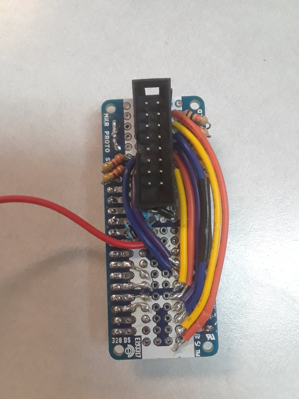
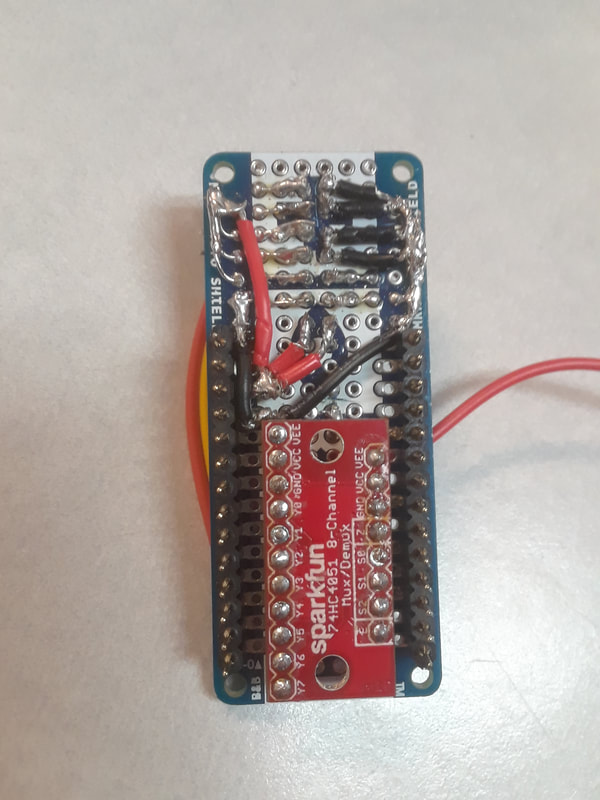
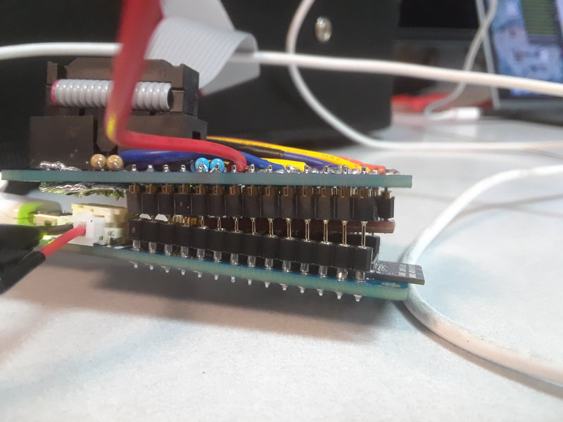
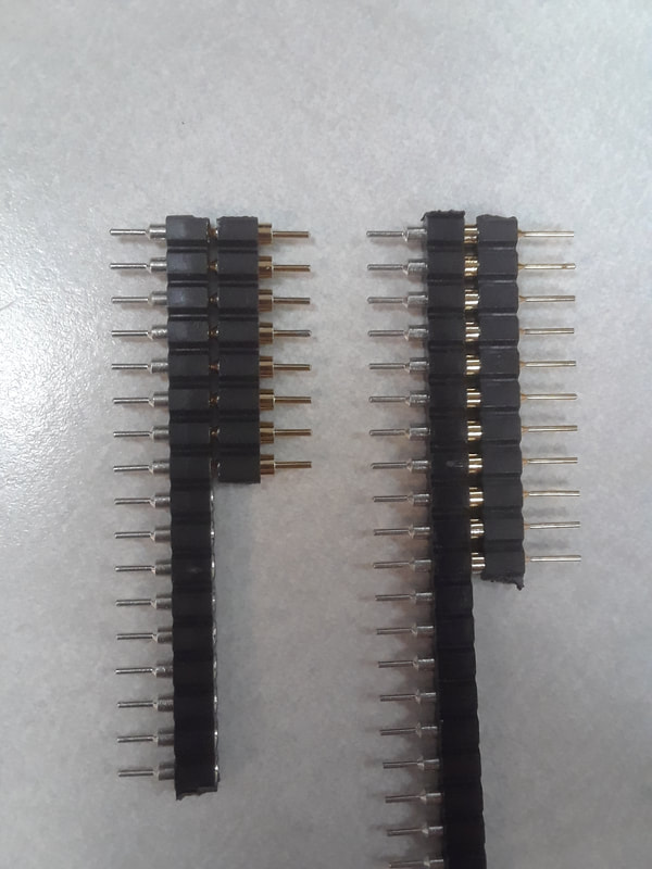
So I tried to re-create the problem to see if it really was shorting out when I am playing. Today I didn't lose connection to the Arduino at all no matter how hard I played on it. However, I did find a problem where I pressed my G string and data bled into my D string. It went away pretty quickly though. Still, I am going to go over all of the connections on the circuitboard with my multimeter to see if I can detect an issue that way, and then go over them again with a soldering iron just to be safe. I have a friend who ordered a custom designed circuitboard for their project. Maybe I should look into that because then there would be fewer DIY solder connections to worry about. Also, I'm not a fan of the Swiss machine headers that I put on my Arduino. They're slightly different from the ones on TRAVIS I and I find the circuitboard has to be tightly held together by the Arduino case in order for them to work. If I had lots and lots of $$$$$ then I would buy a new MKR1000, try out the classic headers and re-print the Arduino case to accommodate the extra height. But alas, I am a grad student who needs to focus her funds on electronic parts for her thesis... :( Since Kindred Dichotomy was accepted into AWMAS 2020, I felt it was time to revisit why TRAVIS I's Arduino Lilypad died. My last visit to the USA with TRAVIS I didn't go so well with the wireless connections, so I am a bit anxious to have all wired backups working.
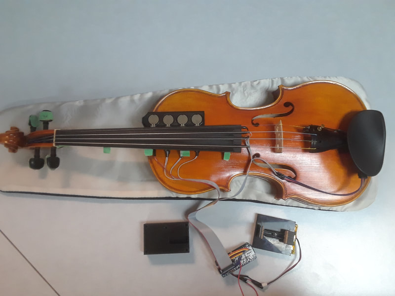
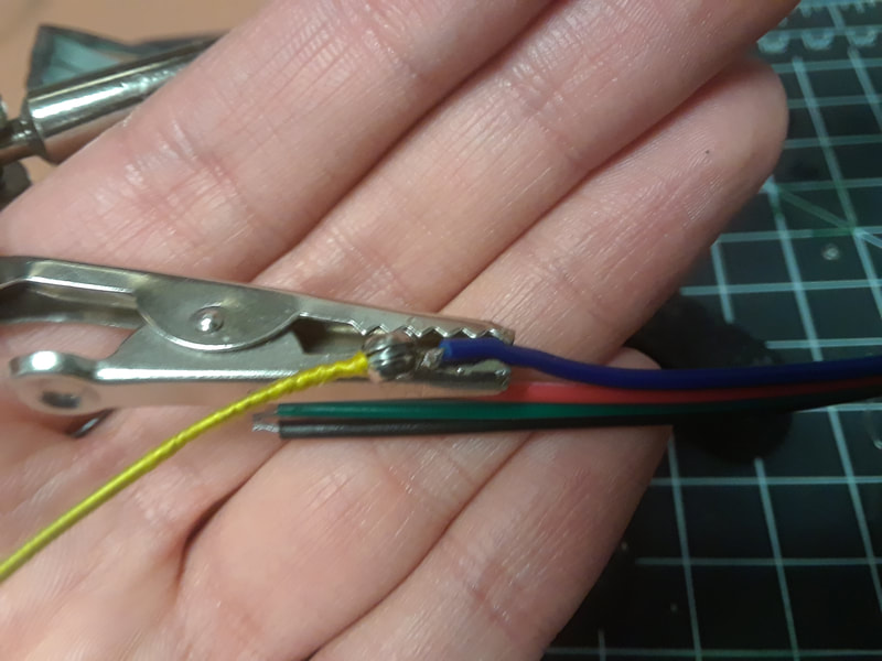
To recap, I was switching back and forth between the Lilypad and the MKR1000 when I was testing something. Then all of a sudden my laptop stopped recognizing this specific Lilypad. Today I still couldn't fix it. But, remember when I posted my comparison of 3 different Arduino Lilypad USBs? It was the blog post on 13/7/2018. I got out my spare Lilypad; it's the one that's not connected to the red glove, and is super jitter no matter what I do with it. When I was making TRAVIS II, there was a slight jitter and I used programming in Max to ignore the jitter when the sensors were at rest. I copied that code for all of TRAVIS I's sensors so now this jittery, "bad", Lilypad is a useable backup. Speaking of backups, the wires on the original circuitboard are starting to be a bit short. So instead of replacing the wires, I am using my backup circuitboard. I made it one summer and called it my backup for my backup, in case the solder cracked and I lost a sensor. I never expected to be using it for this situation. I'll revisit the TRAVIS II arduino code and make a wired version to upload in case it refuses to connect too. Thinking of the worst case scenario, I don't think all of these wired connections to my Macbook will work in a live performance. The audio interface needs to be connected too! It's the dumb macbook pro with only two USB C connections. I can imagine myself or my duet partner pulling out the dongles very easily while playing. I'm going to prepare my old PC to handle the visuals for the AWMAS performance. I think for this reason I should prepare both computers to potentially run either the visuals patch or the audio patch. 3 built in USB connections on the old PC is a blessing. I decided to finally get around to replacing the wires on TRAVIS I so that all FSRs work. I am also slowly working on a duet for both TRAVIS violins, so now is a good time to make sure that both are in tip top shape. I replaced the wires with silicon ribbon wire, so hopefully it won't get damaged as easily as before. It's also black, so it blends in better and is aesthetically pleasing. I wish I could do the same for TRAVIS II, but for that violin I need 16 wires. The most that comes with the silicon wire is 10. I also finally re-printed TRAVIS I's MKR case lid in black filament. I also printed the same clamps as TRAVIS II's design for the FSRs and to hold down the wires away from the strings, so I'm no longer using a clip on the MKR case.
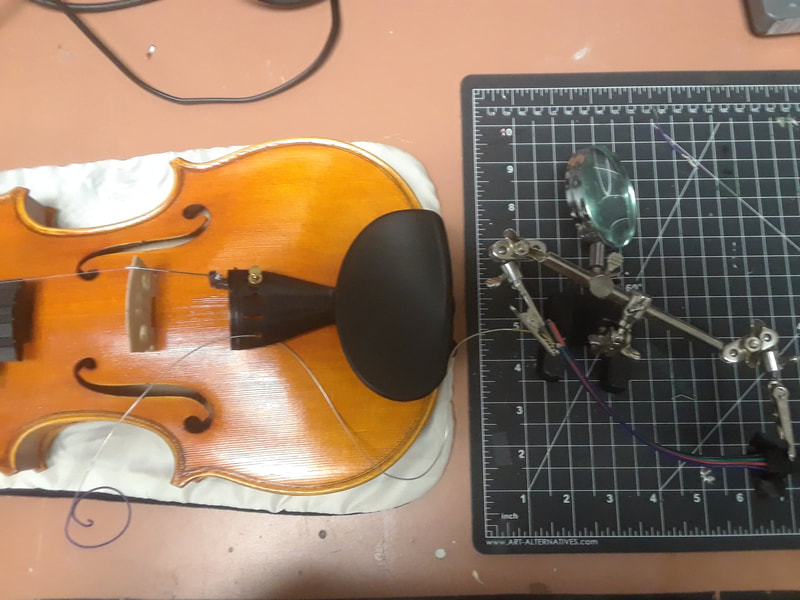
Before I started I tested the ribbon wire with the Lilypad. During this process, the Lilypad died completely and no amount of resetting helps. This makes me sad. I also don't want to spend more money on a new Lilypad since the only one that works is one from China that takes months to ship. RIP original wired prototype. You served well. Re-soldering was terrifying. I didn't want to replace the softpots yet, because they're still working fine. (although dust is accumulating under them and the added height is making the strings buzz. Maybe I should change them soon anyways...) So I had to remove the strings and place a mat on top of the violin to solder. Taking off all strings of any violin family instrument is scary because usually what happens is the sound post collapses due to the loss of string pressure (guitarists usually fall into this trap when changing violin strings for the first time). However, with a strange twist in fate, that didn't happen when I was working on TRAVIS II. So I thought I would take the chance with this TRAVIS I maintenance, and take it in to Aaron if it did collapse. Well, it didn't collapse. One disaster averted. The next terrifying thing was soldering so close to wood, and on a wobbly surface. And the pins of the softpots kept moving because I couldn't clamp them down. It was difficult. It took a while. I hope to never repeat the experience. But it's done and TRAVIS I is now looking extra sexy.
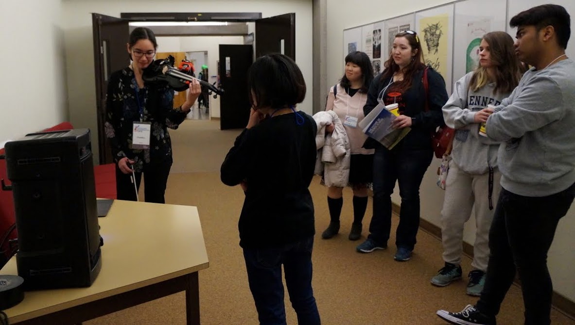
"Dream State" is the first piece made for TRAVIS II. It is semi-improvised. Different sound processes were mapped to each of the four strings, as well as different parameters for the visuals.
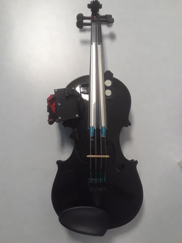
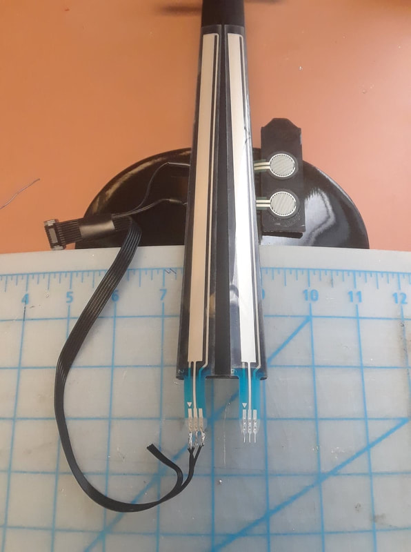
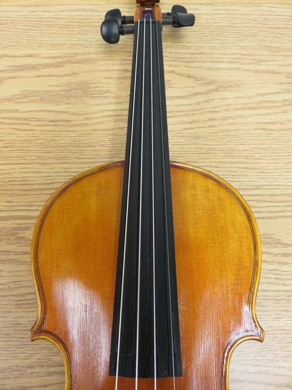
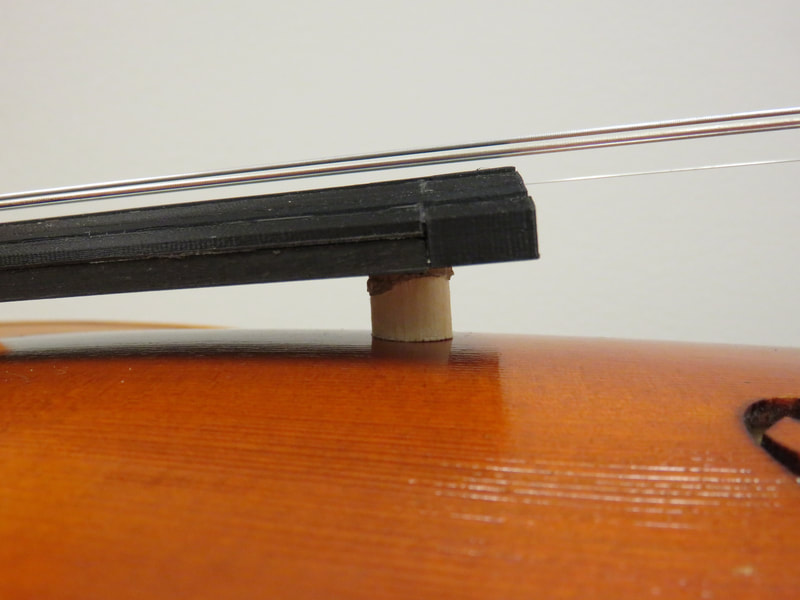
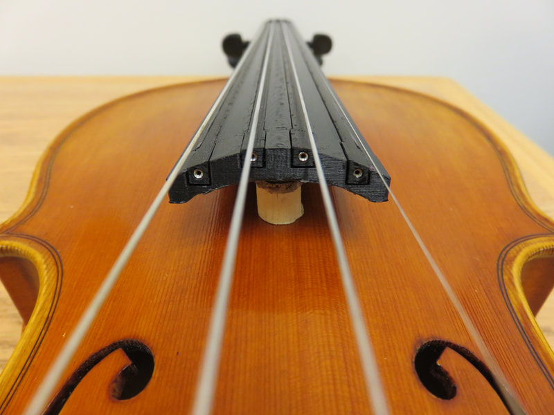
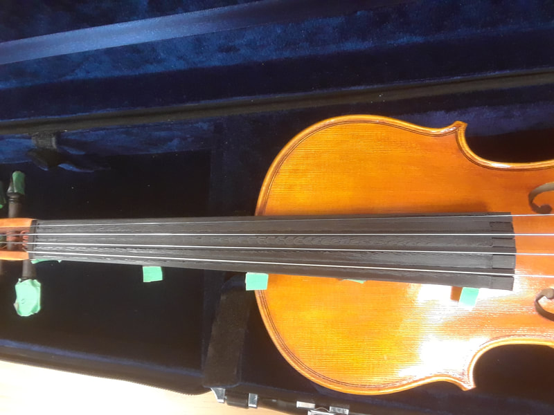
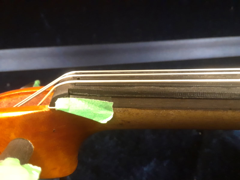
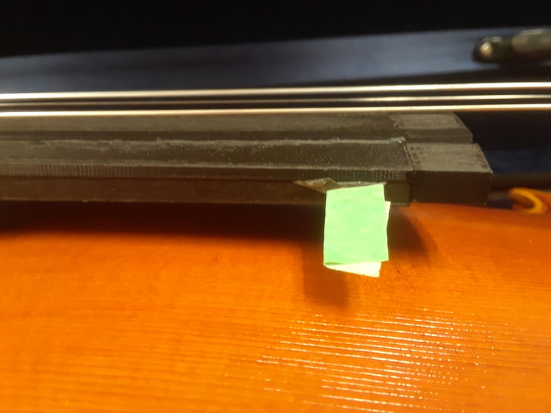
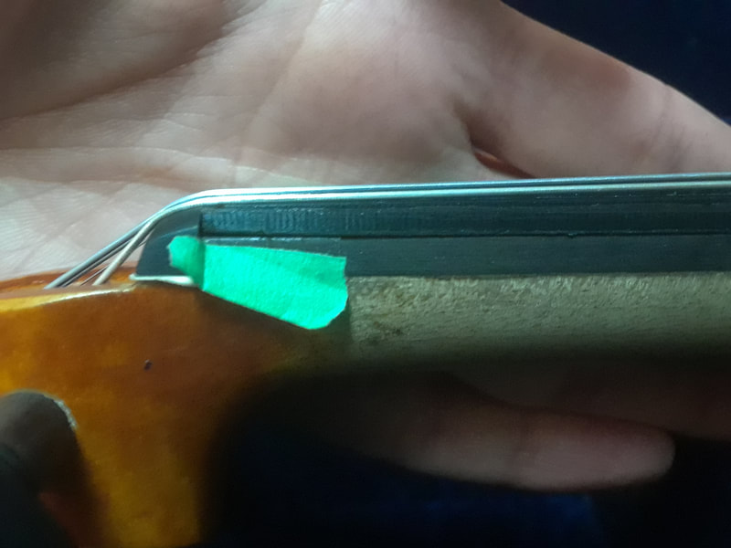
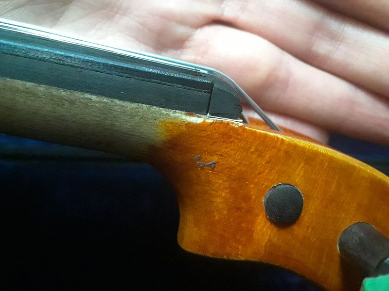
I re-printed the fingerboard to be as short as possible. I also added an undercurve to the header piece. However, I still found the fingerboard to be slightly too high and asked Aaron to shave off a bit from the ebony piece. He did that, plus added a small piece of wood for support. I found that this not only strengthens the fingerboard, but also makes the violin sound better and cuts out the majority of the buzzing that was happening before on certain notes. Now I am only getting buzzing on first finger, G string (A).
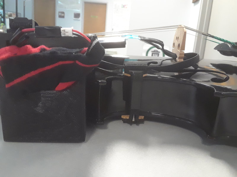
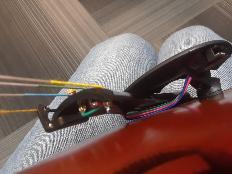
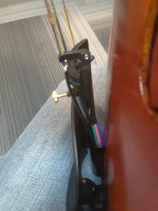
I also shortened the wires and added a clamp to keep the wires down and away from the bow. Had another mess up with soldering the shield. But I got it! I found that the front end still needs pressure in order to work the best. But the Arduino case is snug enough that it provides that pressure. Also, it’s not quite perfect because sometimes the FSRs are a little jittery when they are at rest, and they should not be like that. However, I can fix that in Max because I was previously having the same problem with the Softpots and the MKR (for some reason the Lilypad was fine).
Despite the buzzing, I moved on to working on the Arduino, because for the purposes of a proof of concept, the fingerboard was done. I discovered that the swiss machine headers I have are slightly different from the ones that are on TRAVIS I. For some reason the connection between the shield and the Arduino is fine when it is tilted to the extreme and does not work when it is sitting flat. I think it will be fine if the male to male headers are turned around.
The ebony piece is attached and the PLA part is taped on with scotch double sided tape. I found that the ebony was a little too tall, so my G string was buzzing when I played forte. I can see when looking at the side that the bottom of the header piece is not flush with the bottom of the ebony piece. I think the fingerboard being flat underneath (without an undercurve) makes the sound a little tinny. Certain notes I’m also getting a strange buzzing. Maybe a wolf tone modulator will help to make it sound warmer?
Pay no mind to my poor intonation...
Shhh... you never saw me practicing in the fablabx!
I tested the strips after sanding them and they barely worked. I then took them out of the fingerboard and flipped them over to test the other side. The un-sanded side still worked fine. So, lesson learnt, to not sand the side of conductive PLA that needs to be conductive! I ended up re-printing all of my strips… again. I also sanded the sides of them so that they can fit into the slots, and that was fine, just as long as I didn’t sand the surface.
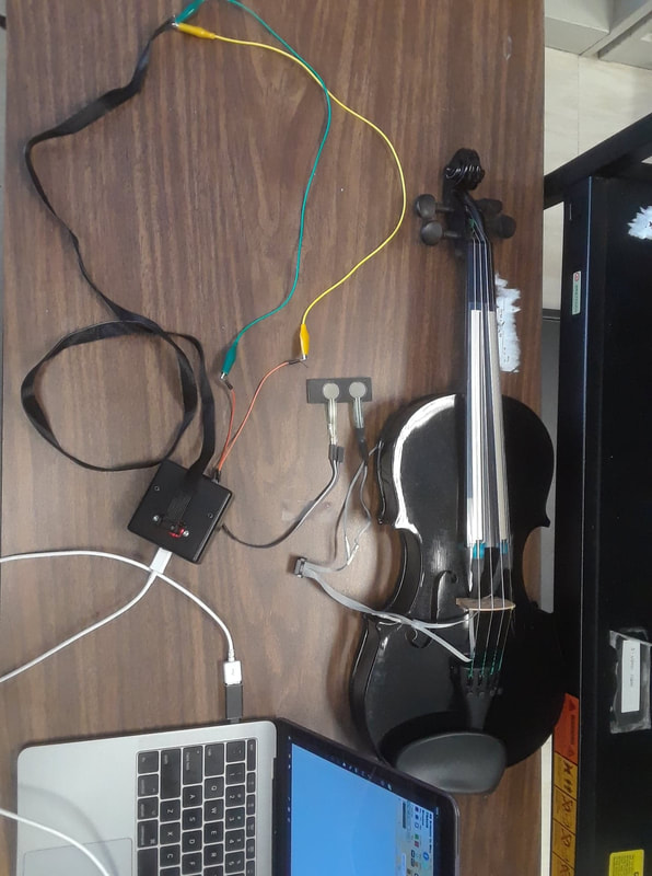
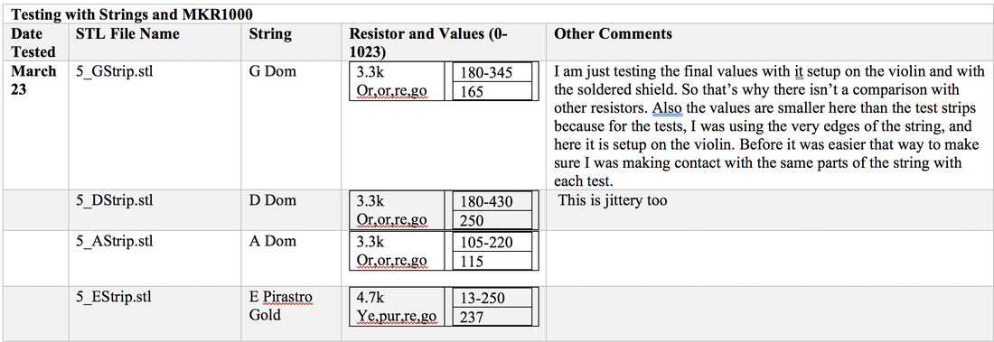
Here are the results for the re-printed strips: 5_GStrip.stl 20MW Close: 0 Mid: 0.01 End: 0.01 2MW Close: 0.002 Mid: 0.007 End: 0.011 200KW Close: 2.9 Mid: 6.4 End: 11.0 20KW Close: 2.19 Mid: 6.67 End: 10.89 2kW: 0L 5_DStrip.stl I noticed this one is a bit more jittery at the 20k setting at the far nut end. 20MW Close: 0 Mid: 0.01 End:0.01 2MW Close: 0.002 Mid: 0.009 End: 0.014 200KW Close: 1.7 Mid: 7.4 End: 12.5 20KW Close: 1.97 Mid: 8.25 End: 16.7 2kW: 0L 5_AStrip.stl 20MW Close: 0 Mid: 0 End: 0.01 2MW Close: 0.002 Mid: 0.01 End: 0.012 200KW Close: 1.8 Mid: 9.5 End: 13.4 20KW Close: 1.64 Mid: 6.63 End: 12.13 2kW: 0L 5_EStrip.stl 20k setting, starting at the middle is a bit jittery. Nut end isn’t too bad though. 20MW Close: 0 Mid: 0 End:0.01 2MW Close: 0.003 Mid: 0.006 End: 0.013 200KW Close: 3.0 Mid: 6.4 End: 11.2 20KW Close: 3.07 Mid: 7.55 End: 10.49 2kW: 0L |
Welcome to the TRAVIS blog!If you would like to see a summary of my work, please click here. Archives
May 2022
Categories |
 RSS Feed
