|
Working away at getting a demo going. So far, I have the IR sensor mapped to an additive synth. I have the amplitude of the partials randomly changing to give it more texture. It was tricky figuring out how to make it so changing the amplitude of each of the partials didn't make pops. I'm working at getting the colour sensor to control the speed of which the partial's amplitudes change. I was trying for the longest time to get the colour sensor mapped onto a [swatch] object, but the saturation kept going down and I couldn't figure out how to make it steady. I instead mapped it to a [jit.matrix] and doubled the brightness with a [jit.brcosa]. When I place any colour in front of the sensor, it shows in the pwindow. But the tricky part is to have useable data to represent each colour in order to use specific colours to trigger other things. I ended up doing a comparison of all three colours in order to tell if the colour is either red, green, blue, or yellow. It's a bit clunky, but for my purposes (for now) it works. Purple appears too similar to blue and orange appears too similar to yellow to be recognized in this manner. Alternatively, I could have used some sort of machine learning to do this, and perhaps be able to differentiate between the whole rainbow (or perhaps not). I should keep this in mind for the future. 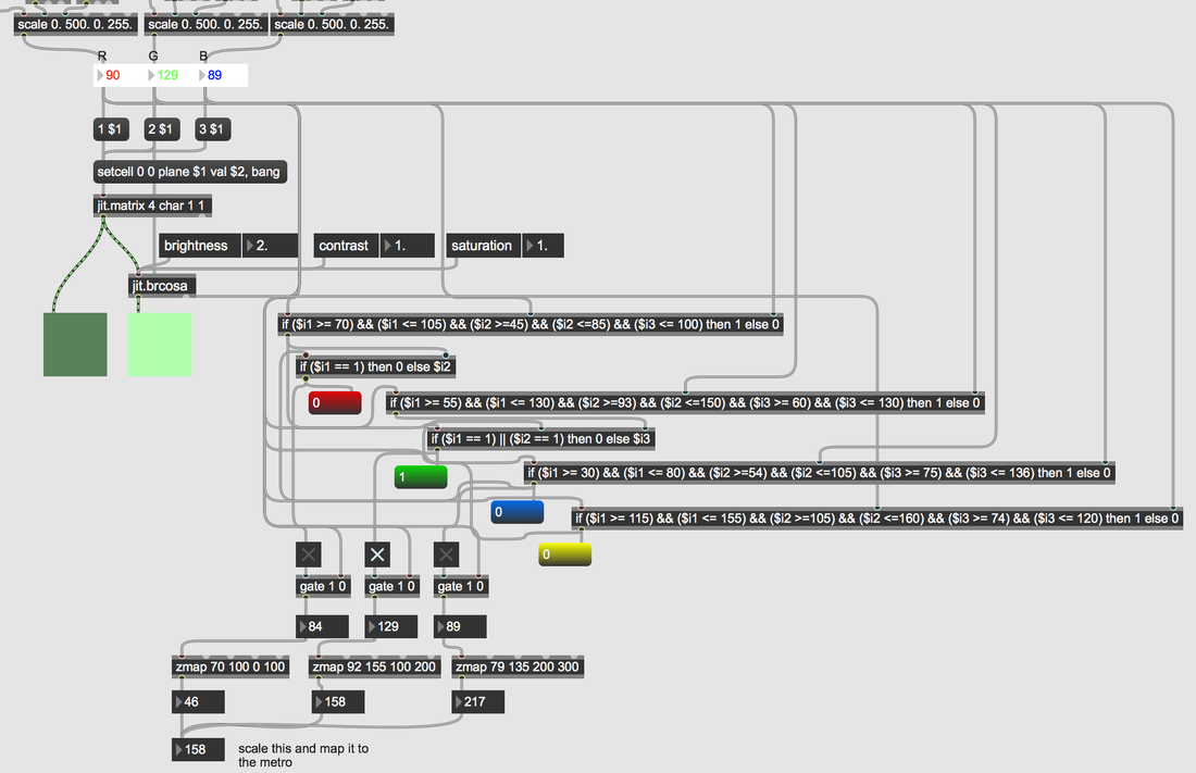
0 Comments
I started to organize my Arduino to Max patch a bit. The RGB values I actually changed the background colours of the float boxes to RGB. I changed the accelerometer data float boxes to light blue. And I changed the IR data box to purple. The order that the FSRs data are printed in are not the order that they are laid out on the ball. This is because I went with whatever was physically easiest/closest to hookup, and that's not always the same order as on the multiplexer (this happened with TRAVIS I and II too). I first organized the layout of the FSRs data in the patch to match the physical layout. This is how it matches up: Right Side: FSR1 = S1 FSR2 = S8 FSR3 = S2 FSR4 = S7 FSR5 = S3 FSR6 = S6 FSR7 =S4 FSR8 = S5 S13 is always a little high when at rest (~450-600). There is an issue with four of the FSRs, mostly on the Left side, in that they bleed into each other.
I thought of taking out the circuitboard and going over the connections again. However, I am sure that all the connections were fine when I tested with a multimeter. Also, I risk making the situation worse and it was very difficult to get all of the sensors plugged in in the first place. I detached the FSRs on the left side that were bleeding into each other and re-arranged them so that the three on the left side are all close to each other. When I moved S16, when I re-attached it, it now sits higher than it was previously when it is at rest. I pulled it off, then put it back on again and then it was back to the way it was. Since that fixed it, I tried the same thing with S13. When I pulled it off, the data went down to where it should be. I think this is because part of the tail of the FSR was bending in a way that it shouldn't and pulling it off the ball straightens it. However, every time I tried re-attaching it, once I press on it again, it would go back to resting high. I'm just going to have to deal with it in Max. The new arrangement is as follows: FSR9 = S13 FSR10 = S11 FSR11 = S14 FSR12 = S15 FSR13 = S16 FSR14 = S12 FSR15 = S9 FSR16 = S10 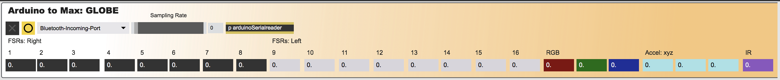 I finally figured out how to solve the problem of Max messing up the sensor data stream through serial! What it was, was one of the [zl group] objects needed a larger number as its argument. Now I just need to come up with a demo and make it completely wireless! Since I am no longer allowed to invite people to play my instrument, and I am going to have to do my performance online, I may change it so I can collect audience feedback from the online viewers. I added sugru to the stand so it is easier to slip paint chips underneath the colour sensor.  I tried pulling apart the FSR wires a little more, but it was difficult. Then I attached the FSRs for good to the ball. If I need to change their placement I can, but I would have to use my double sided tape to re-attach them. I ordered more sugru in order to lift the stand up a bit. Now I really need to fix the maxpatch in order for the lists to not be split up in half.
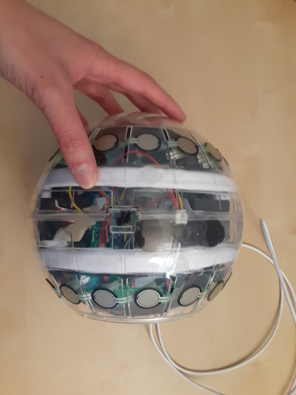
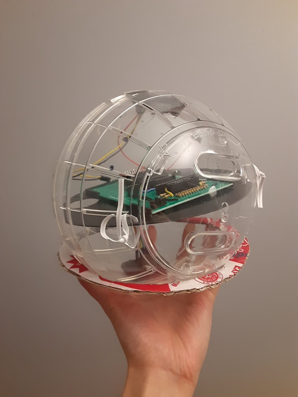
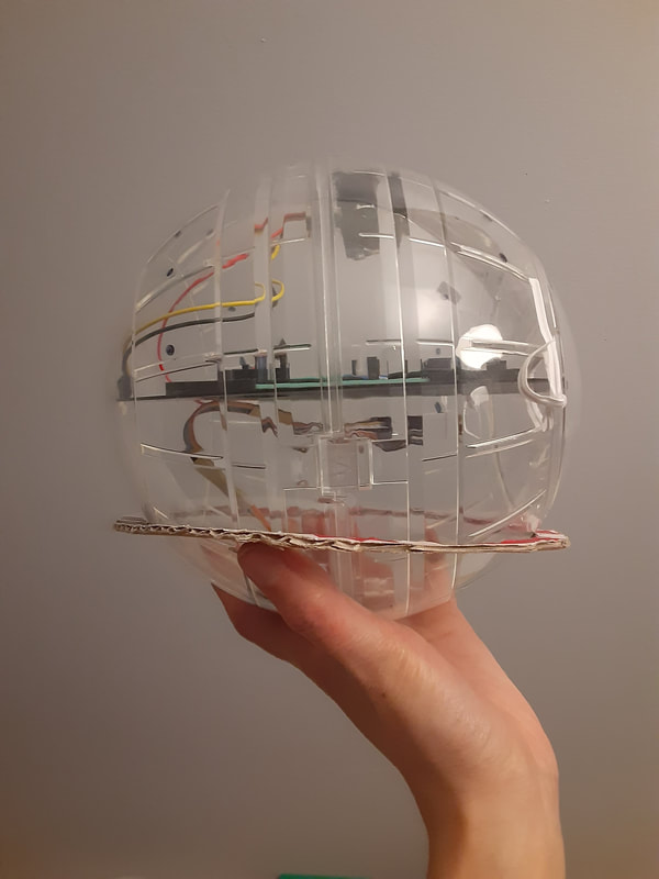
Every time I think I'm just one more step away from finishing the physical side, something else comes up. I hot glued the LED strip to the inside of the ball. It's actually a lot harder than it look to put the ball together with the LEDs attached without accidentally pulling apart the connection for the LEDs in one spot. I should have made that spot's wires much longer. I worked around it by adding an extension to that one joint. I didn't want to ruin the hot glue and pull the LEDs off the ball to lengthen the wires.
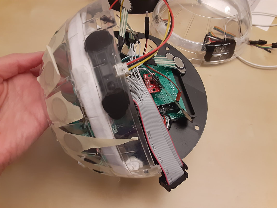
I used scotch tape to temporarily tape the FSRs into place. When I tried to plug everything in, I realized a few things. The wires are much messier in real life than what I imagined. It was much more difficult to plug in everything and I should have gotten a hamster ball that opens on both sides. I should have oriented the USB connector towards the opening. I should have added a battery switch to the circuitboard.
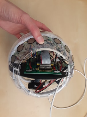
So I unplugged everything and took out the circuitboard and added a switch for both batteries. It would still be difficult to switch the ESP9266 from being plugged into one battery to the other though. I plugged in the USB cable and I think once I go wireless, I'm just going to stuff the cable into the bottom of the ball. Next I'll see if there really isn't anything else I can do to clean up these wires, then I'm going to attach the FSRs for real. Then go back to working on making all the other sensors wireless. I will also have to test if the paint chips can slip under the 3D printed stand easily. Campus has now come much closer to a complete lockdown due to covid-19... yay... so I'm definitely not going to 3D print ever again until I can get my own printer. :( If the stand is too tall, I'mm have to sand it lots, and if it's too short I'll add something like sugru to it to lift it up.
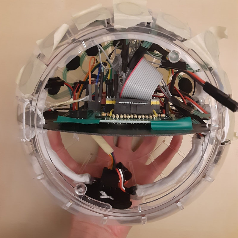
I came to the realization that I shouldn't have soldered the LED strips completely together and should have added connectors at each point. Oops. So I did that and found out that there was a connection/solder problem at the ground header on the circuit board. There was also one connection near the end of the strip where the power wasn't that good, so I fixed that too (I hope). I also discovered that when I turn off the LED on the colour sensor, the readings from it are not good enough to activate the LED strip, so it effectively turns it off too. Now I just need to take out the hot glue gun and attach everything!
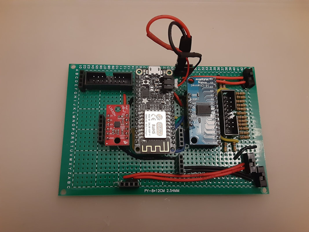
Today I was supposed to work in LabNext. But now most of the workers must work from home. Which means no more 3D printing from LabNext. I went to the fablabx to 3D print a stand for the ball. It may be my last 3D print until I eventually can afford my own machine. While I waited for it to print I soldered the wires onto the FSRs. At first I thought I would use heat shrink wrap with them, but then thought maybe that's not such a good idea with the plastic ends. I'm so close to finishing the physical side! While here I also moved the augmented props back into the iLab. I don't know when, if ever, we are going to do a show with them and I wanted to make sure my colleagues could access them if I leave Calgary before we are through this pandemic :( 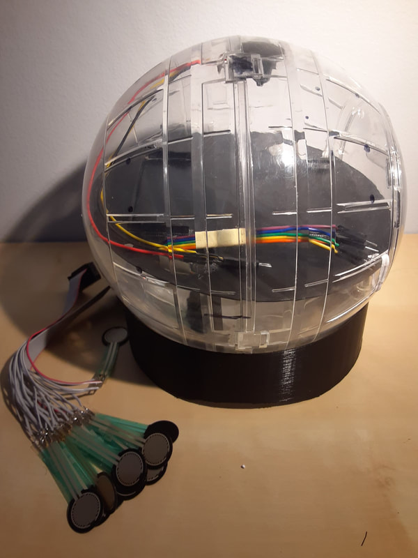 The COVID-19 pandemic has officially affected my thesis, my work, and my personal life. Alchemy Festival is cancelled, I am no longer able to have participants test my thesis instrument, I'm working from home for both my TA position and for LabNext, and even if my paper does get accepted to NIME, the university of Calgary has banned all international travel until September (although, that to is likely to get cancelled). I don't know how I'm supposed to do a public performance with my instrument, because that is a requirement for me to graduate. I modeled a 3D printed stand for the ball to sit in, but I don't know if I'll be able to 3D print it. Maybe I can get creative with some paper mache...? I really just need my own 3D printer at this point. On the bright side, I made some big progress in making my instrument! I successfully got the multiplexer wireless! Now I just need to figure out how to do it for the rest of the sensors. I used sugru to stick the colour sensor and the IR sensor in place. I glued the battery holders on the back side of the disc. I added a switch so I can turn the LED on the TCS34725 on/off. But it requires taking the lid off of the ball and reaching in to the circuitboard in order to switch it. I also added a couple other things to the circuitboard that I realized I previously missed. I planned out where the FSRs are going to stick to. I measured the neopixel strips more precisely to the ball and planned out how they're going to attach. I got permission to borrow the hot glue gun from work. I finally finished marking in class essays and am now back into thesis work.
Due to COVID-19 I've been advised to not get participants to test my instrument. And I just got my first participant to sign the consent forms the day before the university closed (on friday the 13th of course!) :( I asked the polulu forums about changing the time of flight address. Their response is it can be done and to read a specific section of a confusing datasheet. But they warned that since the TCS34725 cannot change its address, there could be issues. Since it's confusing to begin with, and has a risk of not working after all, and I don't know how long it will take for the I2C multiplexer to arrive in the mail, I decided to not use the time of flight sensor for the prototype. I still may add it in the next upgrade though. Trying to get all the work done that requires a makerspace ASAP. I 3D printed battery cases that I will glue onto the back of the disc inside the ball. I 3D printed a little case for the time of flight sensor, even though I'm not sure if I could get it working or not. But I lost the sensor this morning so I couldn't take it with me to measure the case to the sensor. I also sewed tubes to slide the LEDs in to help block the light. I wanted to double layer the fabric, but it was too difficult to sew. If the lights are still too bright, I can dim them more in the arduino sketch, but the dimmer they are, they don't show the true colour as well.
I found the time of flight sensor when I got home. I have made some adjustments to the case and will 3D print it again another time, assuming campus remains open. I posted on the polulu forum asking about changing the address of the time of flight sensor. Apparently it is possible and I'll have to look into it. Of course I find that out after I ordered an I2C multiplexer... I've spent a lot of money for this project on stuff that I end up not using... :( |
Welcome!If you are looking for a summary for my Masters thesis, it is here. Archives
November 2022
Categories
|
 RSS Feed
