|
I was thinking last night about how the IR does not work that great with a 3.3V power supply. Also how the time of flight sensor connects via I2C, and that was another reason why I didn't want to use it because I was previously having troubles getting multiple I2C devices working. Well since I now have both the LIS3DH and the TCS35725 working together via I2C, and the time of flight sensor works fine with a 3.3V power supply, maybe I should see if I can get the I2C code working with the accelerometer and the TCS34725. Even though the IR sensor is better than the Time of Flight, when it is powered with 5V, the Time of Flight works better than the IR sensor when powered by 3.3V.
But when I checked its I2C address, it's the same as the TCS34725. I guess I still have to wait until an I2C multiplexer show up in the mail...
0 Comments
I started looking at the neopixel sketch and realized that when the data stream slows down, it is when a threshold below 150 or below 1000 is met for the "clear". Those are the thresholds for activating frunction1 and function2. Although I couldn't tell what was in those functions that would be slowing it down. I posted on the adafruit forums asking for help for my predicament with the neopixel strip. And the solution was simple: put the " strip_a.show();" outside of certain loops.
I realize that my babbling about this on the blog doesn't make any sense without seeing the code, but trust me guys. This will be so cool! I GOT BOTH THE LIS3DH AND THE TCS34725 TO WORK ON I2C!!!!!!!!
I realized that the LIS3DH has an example of two accelerometers on I2C. I took that example and altered it for the TCS34725. That's another problem solved! This means that I can finish soldering and be sure of how I'm doing it. I started looking at the Neopixels again. I narrowed it down that when function1 or function2 are called, that's when the data starts printing slow. I don't know why. But I feel a little better that I can tell where in the sketch it's going wonky. It turns out my accelerometer wasn't dead to begin with. The ESP8266 just hates SPI devices. The new accelerometer arrived in the mail, when I hooked it up via SPI it still didn't work. Then I tried both through I2C and they both work! I already ordered a Wemos D1 Mini and checked the SPI wiring with it and it doesn't like it either, and again the I2C method works. I checked again with my Arduino Pro Mini to make sure I wasn't crazy and the SPI method does work with it, just not the ESP8266s.
So now I am left with the same problem again, how do I get both the TCS34725 and the LIS3DH to work wirelessly? I thought of a few things:
Feather
I got the Huzzah Feather working with the TCS34725 + LIS3DH sketch. At least I think it's working. It's hard to tell when I'm working with a dead accelerometer. I found a good example of multiplexing a general ESP8266 with the same 16 channel multiplexer that I have. I think it works much better than the other 16 channel multiplexer example I was trying to go off on before. If I end up going back to the arduino pro mini, then I should look at this example again to get the 16 chan multiplexer going. I tried to combine the TCS34725 + LIS3DH sketch with the 16 channel mux sketch, and that's when things got weird. For whatever reason, the feather only printed the mux sensors and ignored the TCS34725 + LIS3DH. I then tried only mux + TCS34725 and mux + LIS3DH. Neither worked. I then went back to the arduino pro mini to see if the same problem occurred. Pro Mini When I first uploaded the new 16chan mux sketch to the pro mini, the data was printing slower than when it was used with the feather. It was like it was slower to update, or the board has a slower processing speed? I then added the TCS34725 and in the serial monitor I can see that the board found it, and printed it's data for the first line. But then subsequent lines it ignored the colour sensor. For the mux code there is a "while (true) {" inside the loop. I moved it to be before the TCS34725 data, so everything in the loop is incased by this function. And it worked! I then did the same with the LIS3DH. Who knew that struggling with the ESP8266 would lead to me fixing my problem with the 16 channel mux!!!!! :) Back to the Feather Same code, just adapted for the different pins now works for the feather too!!!!! So now in my mind, there is something I need to consider. In a perfect scenario where I can add a wifi module to the Arduino Pro Mini flawlessly, should I use the Arduino Pro Mini, or the HUZZAH feather? In a perfect scenario, using the feather has an advantage because I don't have to interface with another module to make the project wireless. On the other hand, if I can get interfacing between the Arduino Pro mini and a module, that also has an advantage; I could use a 5V arduino, have the IR sensor working at its best, and use level shifters to bring the voltage down for the wifi module and the accelerometer. It would take up much more space on the ciruitboard, but all the sensors would be working at their full potential. I'm just going to have to wait and see when the Wemos arrives on Monday! And now for making the Feather take flight...! So many errors... this is what makes horror movies... At first I thought the ESP8266 01 module gets programed like any other add-on to the arduino: program the arduino with the module attached. But no! These are actually different in that they get programmed separately on their own. Before I figured that out I completely uninstalled and re-installed the arduino IDE on my old Windows computer (my FTDI drivers are messed up on my Mac and I need to do deep computer surgery to fix them. I'm not psychologically ready for that yet...). Of course right after uninstalling the Arduino IDE, my windows chose it was a good time to install system updates which take a few hours to complete... When that ordeal was taken care of, I hooked up my ESP8266 to my arduino to program and got this exact error when trying to upload an example sketch onto my ESP8266: https://forum.arduino.cc/index.php?topic=622116.0 The solution that worked for me was to uninstall the latest ESP8266 Community board drivers and re-install the 2.5.0 version of them. But then I got a new error... The new error was this very common one: https://arduino-esp8266.readthedocs.io/en/latest/faq/a01-espcomm_sync-failed.html Also here: https://github.com/esp8266/Arduino/issues/4414 My solution was to not use the Arduino Pro Mini as a conduit to upload sketches and instead connect the FTDI adapter directly. And then as I was uploading the sketch I got a new error... sigh... 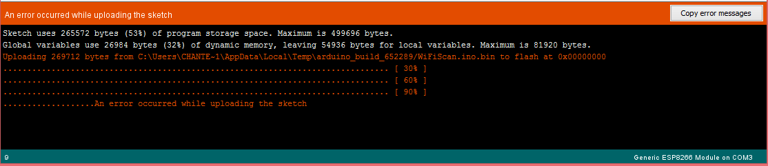 But then I tried uploading again and the previous error came up. I'm starting to feel like this is hopeless! Strangely enough, my HUZZAH feather works perfectly fine. But It only has one analog pin and I was having issues with the 16 channel mux. Also since it's bigger I'll probably have to get a bigger proto-board, if I were to use it instead. :( I then tried increasing the upload speed of the module to 256000. Then I got new errors.... 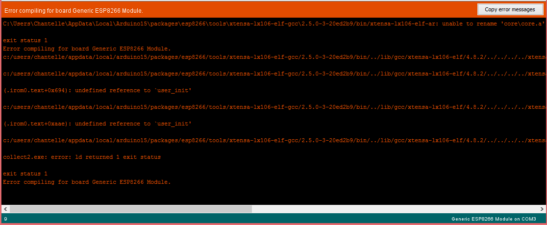 I read in one of the forums that you can upload code to the generic module by selecting the Node MCU 1.0 ESP-12E Module as the board. Aparently they're similar enough that it works. I tried it and the WifiScan code supposedly uploaded. But then when I opened the serial monitor to see if the module was scanning, it wasn't showing anything. :(
I've ordered a Wemos D1 Mini in case if that would work. In the mean time I'll see if I can get by with the feather... :( I started planning the circuitboard and soldered the headers. I'm making it modular where I can unplug any of the main components. I'm not going to solder the connections for the ESP8266 until I'm sure that it works. I'm also going to hold off on the 8 channel mux connections because I'm not 100% sure it's working until I have all 8 FSRs plugged into it. If you have just one plugged in, it goes a little weird. I'm not sure if it's advisable to have the S0-S3 pins in the opposite order from the initial examples, but it is easier to solder this way. There is no space to add a level shifter, so if I do alter it to a 5V arduino, I'll have to make a new circuit board. 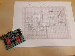
I took a break from trying to troubleshoot the ESP8266 and started planning out my circuit board. I started having more troubles with the 16 channel analog Mux. I realized that if I used the same 8 channel mux as TRAVIS II, that I'm much more familiar with, and read the remaining analog pins on the arduino, then I still have the same number of analog sensors that I initially wanted. So I altered the arduino code for that. Maybe I'll look at the 16 channel Mux again in the future.
I tested the IR with my quad level shifter. It's supposed to be able to shift the voltage both ways, 5V to 3.3V and 3.3V to 5V. But I couldn't figure out how to shift it up to 5 for the IR sensor. Then I realized that if I got a 5V arduino pro mini, the only issue would be the LIS3DH and the ESP8266 which are only 3.3V. I decided to try the LIS3DH with my Arduino Uno, hooked up to the 5V and the level shifter. That was a mistake. I didn't hook it up right either and completely fried my accelerometer. Now I have to wait for a new one in the mail..... I also ordered a different level shifter that Sparkfun specifically has a tutorial on how to connect the LIS3DH to it. That way if I do switch over to the 5V Arduino, then I'm less likely to mess up. For now I'll get by with 3V only and the IR sensor will just not work ass well as it could. I decided I'm fine with the ADXL337. One thing it doesn't show clearly is when the accelerometer is turned all the way upside down. Otherwise it's workable.
I integrated it with the Mux and the TCS34725. When I was testing it, two things that were weird happened. 1) My computer refused to properly upload sketches to any Arduino Pro Mini. I restarted my computer and it then uploaded sketches fine for a little while. But as I was watching it print data, after a little while it stopped. If I restarted the serial monitor, it would start printing data then again it would stop. I tried unplugging then plugging it back in again, and then it stopped properly uploading sketches. I think this must be something with the FTDI and drivers. I've heard of people having issues with it with Mac. If I can't get it working again, I'll see if I can get it to work on my old Windows computer. But it will take a bit to transfer everything I need onto my Windows to get it going. For now I'm back to testing with my Unos. 2) Max MSP does not like printing out lists from the arduino that are larger than 19. If for example I have the arduino printing a list of 22 bytes, Max would split the list into two: 18 byte list, then 4 byte list. This is not right, especially since the zl object's max list length is 256. I think I'm going to troubleshoot this later because it is much easier for me to fix Max than it is to fix arduino codes. And I still need to finish the Arduino codes. Edit: I'm not liking the NRF24l01 at all anymore. I just want the ESP8266 to work... if I can only just get it working, then I can go back to the other accel too... The skipped data issue with the Arduino has been solved. All I had to do was bump up the baud rate. But I'm keeping my workaround in the Max patch as a safeguard.
Now the ESP8266 is giving me grief... I woke up with a brilliant idea. What if I solder in headers to the circuitboard for both the NRF24l01 modules and the ESP8266 module. Before I was able to get the NRF24l01 working to send one analog sensor data to another NRF24l01, then the receiving arduino it printing out the data into the computer through the cable. If I could get it to work for all my sensors, then I can move forward with my instrument prototype, solder the circuitboard and take my time troubleshooting the ESP8266. When I am ready for the ESP8266, I can just easily unplug the NRF24l01 and plug in the ESP8266. One problem. The NRF24l01 uses SPI. Previously I couldn't figure out how to use I2C busses to have the LIS3DH work with the TCS34752. That's why I plugged the LIS3DH in using SPI. I tried to figure out how to have two SPI devices, but when I uploaded my code, I did not see any data being sent to the receiving NRF23l01. It is difficult to troubleshoot whether this is a wireless problem or a two devices using SPI problem. I looked it up and I'm not the only one who struggles trying to get the NRF24l01 to work with other SPI devices. Then I thought of another workaround. Before I was comparing the LIS3DH against the ADXL337. I ultimately picked the LIS3DH because it was very exact about its orientation with 1's, 0's, and -1's. The ADXL337 gives more of a loose range for each of the xyz data. Therefore it would require a little more Max programming. However, it is an easy workaround to my problem. It uses three analog pins to send its data, not SPI or I2C. So it would not cause me any grief for making the Arduino sketch work for it and my other sensors. So now I have a new "to-do". 1) Test the simple ADXL337 example code to be sure I want to go with this workaround. 2) Make sure I am able to use this with the rest of my sensors, and the mux through serial. 3) Combine the giant sketch with the NRF24l01 |
Welcome!If you are looking for a summary for my Masters thesis, it is here. Archives
November 2022
Categories
|
 RSS Feed
