|
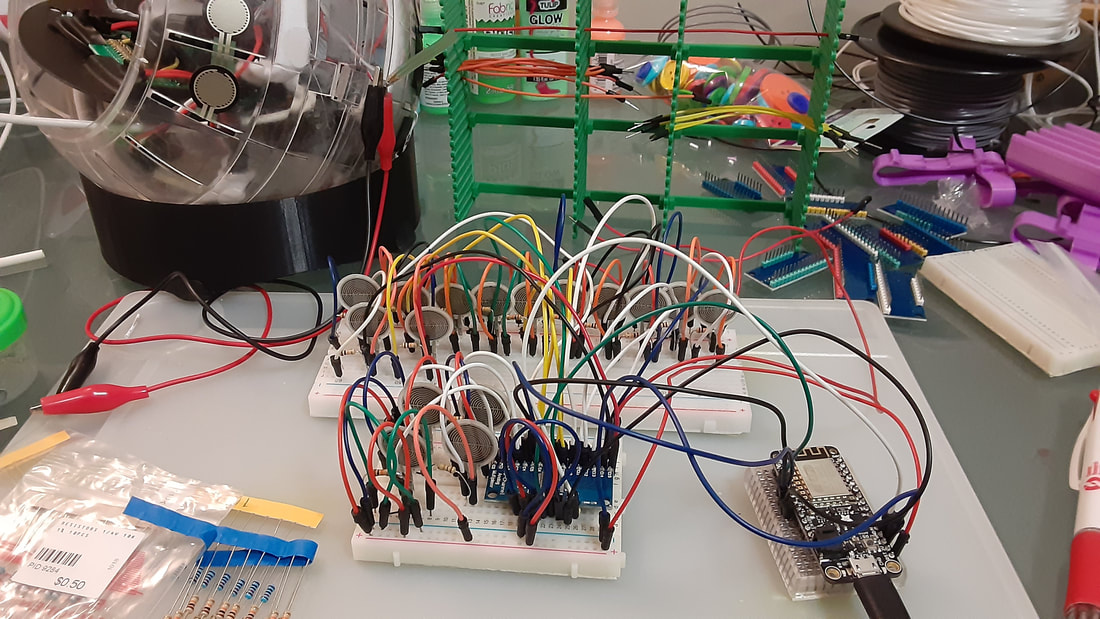
I did a full clean and re-organization of my work area. In the process I found an old arduino uno kit that was given to me. It had what looked like a much better breadboard than what I used previously, as well as little connectors that make the breadboard look cleaner when used instead of jumpers. So I re-hooked everything up with the new board, plugged the resistors into ground directly instead of connecting them with a jumper, and used the little connectors from the kit to connect the FSRs to power.
With this testing, pins 15/16 no longer bleed! I got a little bit of bleed on other pins, but I am pretty sure that it was more caused by knocking wires with my hand. Also, when this bleeding occurred, it was just like a little nudge on the pin; it was not like I was pressed on two FSRs identically, like how it was behaving before. If this happens in the final version of the new GLOBE, then it could easily be accounted for in programming. This means there is something connecting the 15/16 pins on the current GLOBE. I am always so careful of checking all of the connections on the circuitboard though. I am suspicious of the wiring itself. Since knocking the jumper wires of my test was enough to make them bleed, it makes me think that perhaps the mess of wires inside of the GLOBE could be at fault. I still think that a problem this small is not worth taking apart the GLOBE to fix, because that risks making or worse or causing other problems. This will be improved for the next model. I hope to learn how to design my own custom PCB, and re-design the layout so that the wires that connect to it stay as neat as possible. I was just thinking about what configuration made it easiest to solder when I was first making the GLOBE, which is what resulted in the current birds nest of wires.
0 Comments
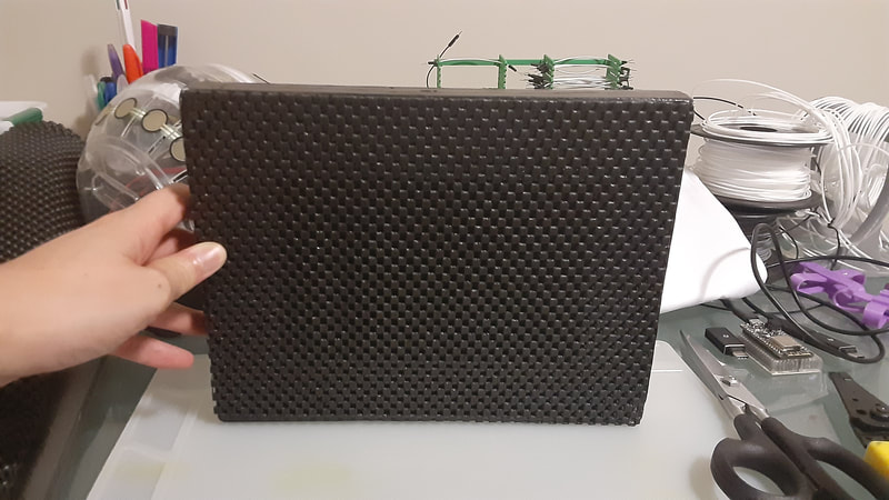
I'm basically improving as much as I can without having to actually build a new GLOBE. Then onwards to making my next piece! I taped an adhesive sheet to the bottom of the new spinning stand to give it some grip.
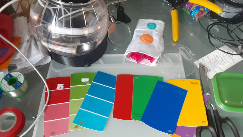
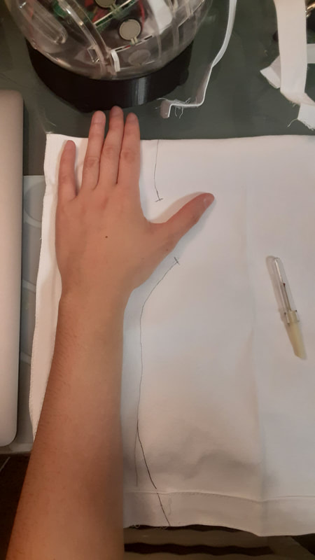
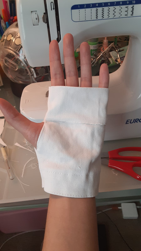
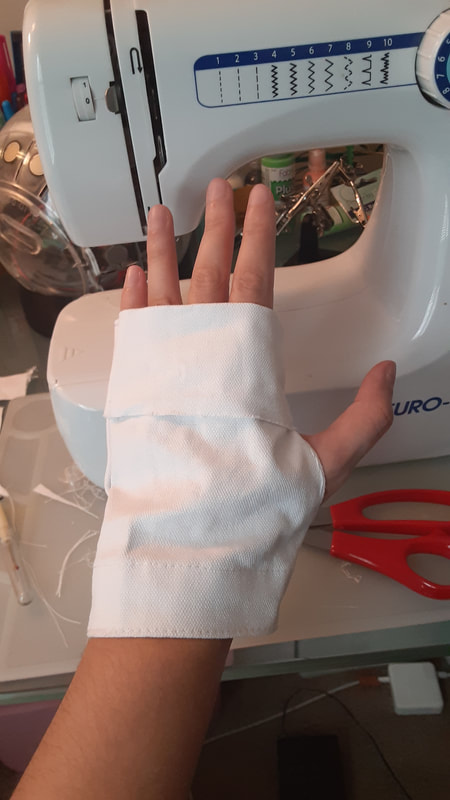
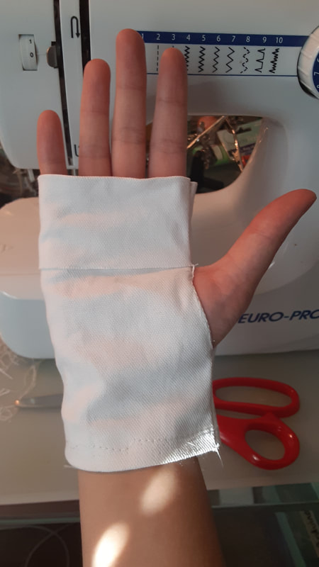
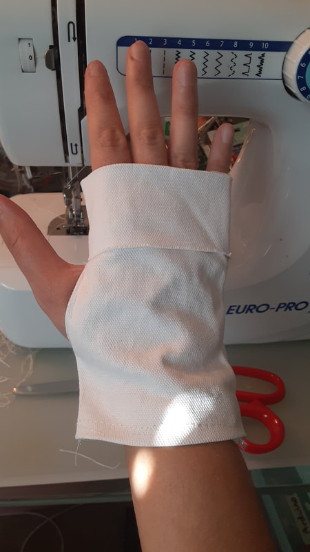
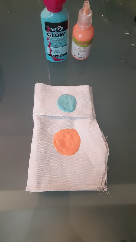
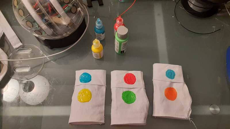
I soldered in the replacement FSR. I also extended a couple power wires that were being strained. There are several wires that are too long now, but that is better than too short and things getting unplugged or damaged. I also took apart a bag that's fabric is made specifically for fabric paints, and sewed it into fingerless gloves. I got the measurements wrong at first, but I had just enough leftover fabric to get it right. I used one of the failed attempts as a first try at seeing where I wanted to place the colour blobs on them. Then I moved on to add the RGBY paint to the actual gloves that I will be using. I got more paint chips for using with the stationary, 3D printed stand, because my old ones got ripped a bit. Also I wanted large rectangles with single shades and not little multiple shades on one piece. And lo and behold the RGB colours that I grabbed were not being picked up by the LEDs. This further proves my assumption that the GB paints that I initially tested were not working because the shade of the colour was too dark. The lighter samples of the old paint chips work well. So I need to make another visit to Home Depot to pickup lighter shades. The yellow, purple, and orange chips that I got worked well. Moral of the story, always plan your trips to home depot and bring your previous paint chips with you. Impulse visits to the paint section do not always work out. There was a bug in the Arduino sketch that was introduced when we first made it so that Max MSP sent brightness values to the ESP (Oct 2021 version). The ESP was refusing to print any data through serial unless it firsts connects to the wireless network. Kevin fixed it. Now it behaves the way it did before where you can easily use either wifi or serial. Kevin also worked on optimization. Now the loop prints much faster than previously, which is great for musical instruments. https://github.com/CLKo1/GLOBE_esp8266/tree/main/Dec19_2021_NoPass
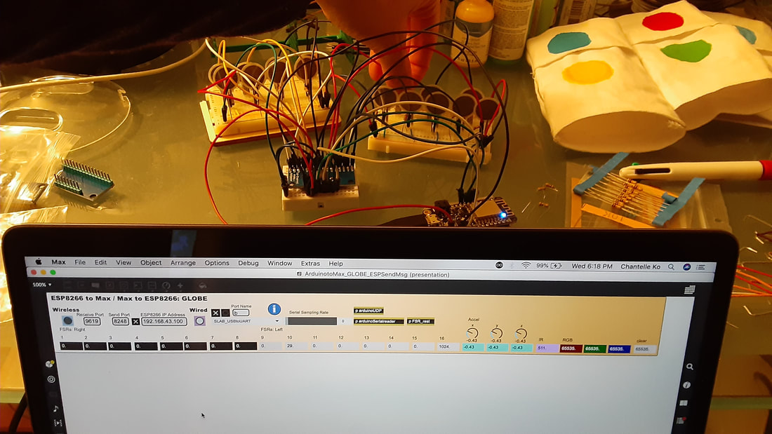
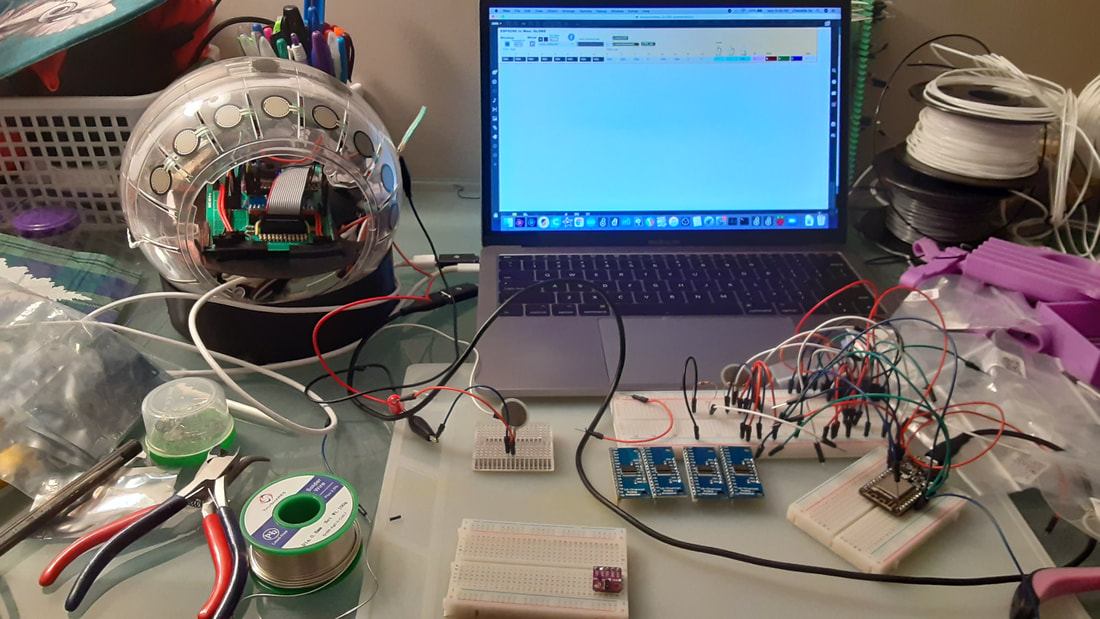
I hooked up my new 16 FSRs to the breadboard, with the original multiplexer, and new HUZZAH feather. The results from that... well.. proved that I probably need more reliable breadboards. Still, I did notice that when I pressed on the FSRs for pins 15/16, they still bled into each other. But, pin 15 was not resting at 0, whereas pin 16 was resting at zero. I also tested each FSR individually and they all work well. I believe it's just the connections in either the wires or the breadboard itself that is causing it to go a little crazy. Now I'm wondering if I have another breadboard somewhere that I lost during one of my many moves. I don't remember having this problem the first time around with testing on a breadboard.
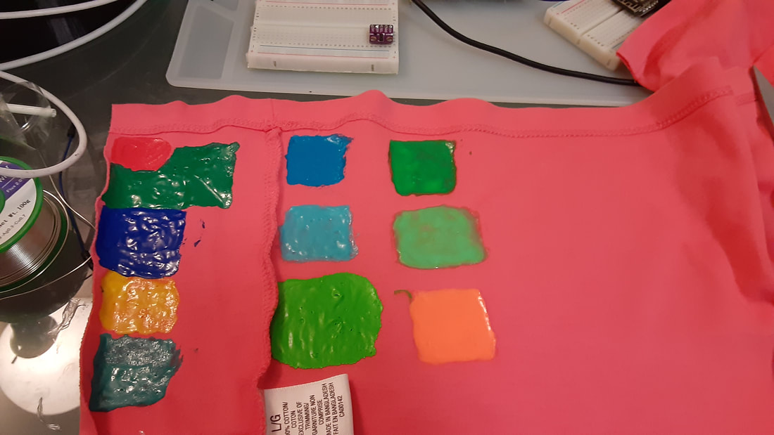
In the end, I'm still not sure if it is the multiplexer itself that is allowing pins 15/16 to bleed, or if it is my circuitboard and breadboard that both are messing it up. Maybe the only sure thing to do is finally learn how to design and order a custom PCB for my circuitboard. I got more fabric paints to try, and I was right; it does work better with lighter shades. All of the new paints work well. In the picture I like the top blue and the bottom green the best out of the new ones. That green is a different brand from the rest of the colours and it isn't as shiny. I think overall I like that non-shiny look better, but the paint bottle itself has a bit of a difficult applicator than the other bottles. I would have to use a paint brush to use it accurately. The lighter orange still looks fairly close to red. I also noticed that these fabric paints soak right in to the fabric. So I bought a bag that is made for these kinds of crafts and plan to take it apart and sew it into gloves for performance.
I also finished soldering headers to all of the 16 channel multiplexers that I had. I mix-matched different colours so I wouldn't confuse them. 6. Green/Red: 4/5 bleeds, 1/5 bleeds, 9/12 bleeds, and 10/15/16 bleeds. 7: Blue/Yellow: 1/15/16 bleeds, 13/15/16 bleeds 8. White/Red: Most pins read values around 41-43 (pins: 2, 4, 6, 7, 8, 10, 11, 12, 13, 14). Pin 3 sits at around 901-904. Pin 5 sits at 1024 and is unresponsive (all the rest do work even if they sit at strange values) . 15/16 bleed. 9. Red/Blue: 13/15/16 bleed. It was then that I noticed that when 13 is triggered, 15/16 or always lower than 13. So it is easy enough to program to ignore that and only trigger 15/16 when their values are much higher. 10. Blue/Green: 2/15/16 bleed (pin 2 is like how pin 13 behaved last time). 13/15/16 bleed. 11. White/Yellow: 13/15/16 Pins 15/16 consistently are equal with all of my chips, no matter what else is happening. It makes me think perhaps there is something that I missed that is causing that. I will test with one of the best boards and hook it all up with other FSRs and my other HUZZAH feather to test. If it has identical behaviour with the breadboard as the with the main circuitboard, then I know it is something that this chip does. So in reality it might actually be more of a 15 channel multiplexer than a 16 channel one. False advertising! I've been selected as a finalist for the Guthman Instrument Competition 2022!
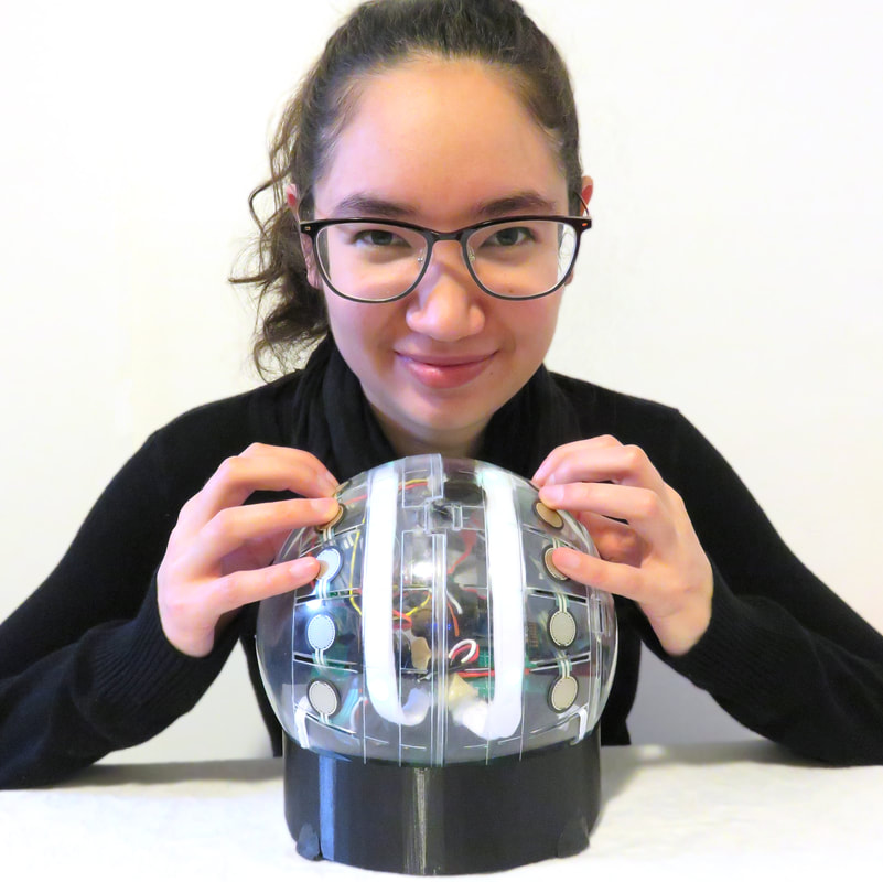
I've been assembling parts for a new version of the GLOBE. I'm still a long ways off. But I thought I would test out the FSRs and the 16 channel multiplexers. I haven't gotten around to testing every FSR, but the one that I did test works well. I felt unsure if the issues I was seeing with the multiplexer was due to a bad breadboard or if it was the multiplexer. So I plugged it in to the GLOBE since I made the parts modular. It turns out you never know how good these boards will be. Also, I am pretty certain that the issues with a few bleeding pins in the original have more to do with the board than my connections. I have multi-coloured pins, so I am using different colours on each multiplexer in order to keep track. I have only tested 5 so far before having to call it a day.
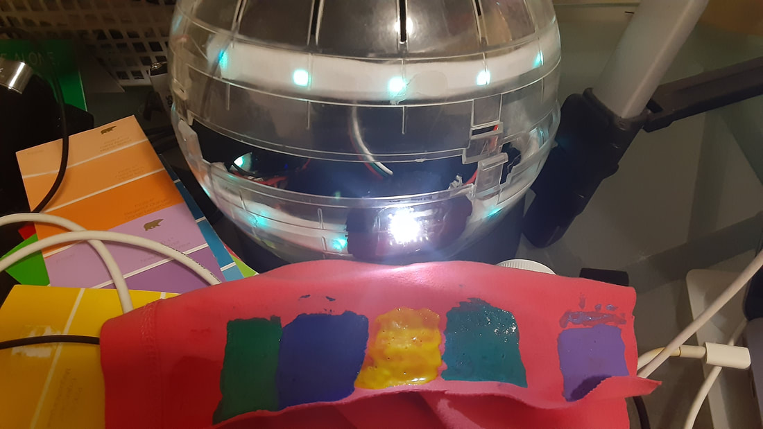
So the turquoise and the lavender samples work very well. Blue I got to work a couple times, but it is very difficult. I had to keep trying and moving the blue sample around until it would change the LEDs. The green just was not working at all. I think maybe I'll go over the blue with another layer of paint, and make the green larger, and try these colours one more time. Or perhaps there is something about the way these particular paint colours reflect light that is not so friendly with the colour sensor.
If my memory of my childhood is correct, I think I had fabric paints that dried a lot faster and were a lot thicker than these ones before. These paints seem to soak through the fabric a lot more and take 4 hours to dry. I may visit Michaels soon and see if they have any other brands to try. Update: After going over the green and the blue one more time, the blue is not any better. I was able to get the LEDs to register the green once. This is not good enough results for a performance situation. These two shades are darker than the other paints, so maybe it has to do with that. The orange also works, but I find it looks rather similar to red with the LEDs. I'll look to see if there are lighter blue and green paints that I could try. Another note, I think I may have written about the wired connection issue already (can't remember). Basically, the ESP8266 refuses to spit out data through serial unless if the computer is connected to the wireless network first. Then after it starts printing the data through serial you can disconnect the wireless network and it is fine. This didn't start happening until we added the update to send brightness data from Max to the GLOBE. It hasn't been a problem so far since I'm not doing public performances where that backup method is needed (yet). While I was testing for the colours, I noticed that the GLOBE refuses to turn on its LEDs or change colours unless if it first connects to the computer wirelessly - which I think is related. It's like the ESP will not do anything until after a handshake is made, which is hopefully something I wish to fix (though it's lower on the priority list). I figured out a much much MUCH better way to detect colours with the colour sensor. It turns the RGB data into HSL, and then the H is mapped to MIDI. There are far fewer chance of accidental false readings this way. An updated bpatcher for colour detection is posted to my GitHub: https://github.com/CLKo1/colourdetect-maxmsp
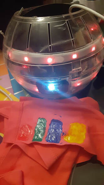
I have an idea of having the different colours on gloves. The thing is the colour sensor does not work with fabric. I had the idea to test 3D fabric paint with it. I remember from my childhood that this kind of paint has a flexible plastic-like texture once it drys. So I went out and got a set of 3D fabric paint from Walmart to test. The Red works very well! The rest I had to go over them and made the samples larger in size. Then the Yellow worked well. The Blue and the Green definitely showed well inside of Max. But the LEDs did not change colours. So I am going over the blue sample again to make it wider. I also made a lavender/purple sample and a turquoise sample. We will see once they dry if they're okay. If I can get the blue working then I will try green again. |
Welcome!If you are looking for a summary for my Masters thesis, it is here. Archives
November 2022
Categories |
 RSS Feed
