|
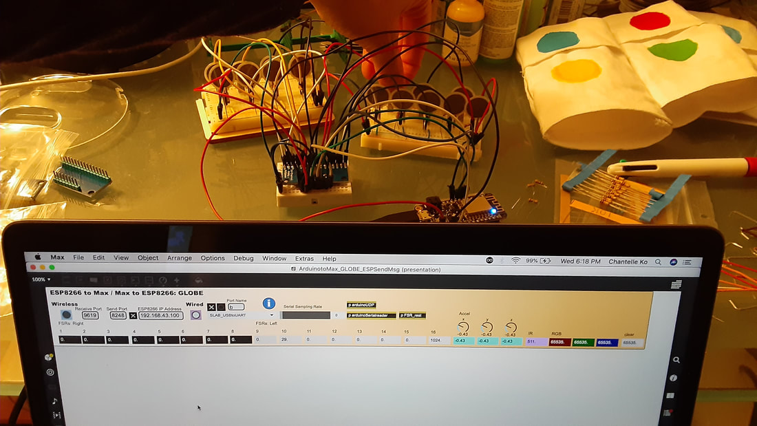
I did a full clean and re-organization of my work area. In the process I found an old arduino uno kit that was given to me. It had what looked like a much better breadboard than what I used previously, as well as little connectors that make the breadboard look cleaner when used instead of jumpers. So I re-hooked everything up with the new board, plugged the resistors into ground directly instead of connecting them with a jumper, and used the little connectors from the kit to connect the FSRs to power.
With this testing, pins 15/16 no longer bleed! I got a little bit of bleed on other pins, but I am pretty sure that it was more caused by knocking wires with my hand. Also, when this bleeding occurred, it was just like a little nudge on the pin; it was not like I was pressed on two FSRs identically, like how it was behaving before. If this happens in the final version of the new GLOBE, then it could easily be accounted for in programming. This means there is something connecting the 15/16 pins on the current GLOBE. I am always so careful of checking all of the connections on the circuitboard though. I am suspicious of the wiring itself. Since knocking the jumper wires of my test was enough to make them bleed, it makes me think that perhaps the mess of wires inside of the GLOBE could be at fault. I still think that a problem this small is not worth taking apart the GLOBE to fix, because that risks making or worse or causing other problems. This will be improved for the next model. I hope to learn how to design my own custom PCB, and re-design the layout so that the wires that connect to it stay as neat as possible. I was just thinking about what configuration made it easiest to solder when I was first making the GLOBE, which is what resulted in the current birds nest of wires.
0 Comments
Leave a Reply. |
Welcome!If you are looking for a summary for my Masters thesis, it is here. Archives
November 2022
Categories |

 RSS Feed

