|
I took out the function1 in the Arduino Code and made the "clear" print through both serial and UDP. It really does act like a proximity sensor and makes it simple to get the colour sensor to ignore sensing ambient light. It will be helpful in that I don't have to sample the ambient light for my twister mat piece, and make it so it more accurately recognizes green. (hopefully, I still need to test).
I also realized that in order for the data to print through serial, the ESP8266 has to first make the wireless connection. The router can be unplugged after the connection is made and the ESP8266 can still print out the data through serial, it just needs the initial connection. This was the same with TRAVIS I. I figured out that what is happening, since it couldn't connect to the network, it was stuck printing out "..........", which is what it is supposed to do. If I commented that part of the code out, then it works fine through serial without having to first make a wireless connection. The only downside is there is now nothing to show me that it is clearly a wireless issue. However, the dots wouldn't show clearly in Max regardless, so it doesn't make a difference for how I'm using it. Since I took out function1, I renamed frunction2 as function1, and function3 as function2.
0 Comments
I am almost finished the patch for my second piece with the GLOBE. Last night I was playing around with it on the twister mat some more. I noticed that it had a tendency to trigger red more often, which was fixed by sampling the ground as "off" and ambient light as "orange". However, the ambient light was very dark, and the green circles on the twister mat is also very dark. So that made it accidentally trigger "orange" when I actually meant for it to trigger green.
I slept on the problem and I remember that there are three functions in the arduino sketch to drive the LED's. They are based on another value coming off of the colour sensor I think it has either to do with proximity or overall light levels. I can't remember, got to check again. But basically it allows the LEDs to turn off if the sensors "sees" black, and for them to maintain their previously sensed colour of the sensors "sees" ambient light. If I can modify the Arduino code to spit out that value, I could use it to program the colour detection similarly, where it will sense a colour if it is close and ignore if it is ambient light. I also thought it would be good to take out that LED turn off function in the Arduino code to better reflect what is happening with the sound. At first I thought it would be a better idea that when one battery dies, to unplug the battery wires from the HUZZAH and plug them into the other battery. But since it is more difficult than anticipated I added wires so that the HUZZAH will be plugged into both batteries at the same time. I just need to be extra careful to not turn both on at the same time. I also extended the battery wires so that they are easier to unplug/plug in. I also extended the wires on my Adafruit lipo charger. Hopefully in the future all of these modifications make it easier to charge the batteries. Still chugging away at the second piece. I've chosen a bedtrack for each of the colours, red, green, blue, and yellow. I don't think I'll do purple or orange. I've also decided on what audio processes to use for the green, red, and blue. Now I just need to figure things out for the yellow. I chose Bees for the yellow bedtrack and it's proving tricky to figure out what I can do with it that sounds good. 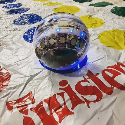 I've been trying to come up with pieces for the GLOBE. My advisor said that I should focus on two contrasting ones and that they don't need to be too complicated; they just need to be able to demonstraight concepts very clearly.
A week or so ago I put together a patch to show off what it can do and roll the ball around on the floor for fun. I did it very quickly and I'm not much of a fan of the patch. So I'm starting over. I turned the colour detection part of the patch into a bpatcher because I know I would use it a lot and it's possible to use it for anything that outputs RGB data. I initially thought of doing one piece per playing technique that I came up with, for a total of four pieces. But that's too much. So I'm going to do one piece with the ball being constrained to its original hamster ball stand. This one will only use the accelerometer and the FSRs, it is mostly 1-to-1 mapping with little automation, and it will only use synths and possible MIDI. The other piece will have playing the ball on its 3D printed stand, picking it up, and rolling it on the ground. The sounds will be from recordings and possibly physical modelling. So far I've worked really hard on the accelerometer for the hamster ball stand piece. I mapped it to a droning synth that's made up of adding many together that are slightly detuned. They are sine, sawtooth, and rectangle waves. The position of the ball when it's spinning controls the cutoff of the filter, and the amplitude of each of the individual synths. The speed of which it spins controls the height of the Q on the filter. Other parameters are automated. Edit: I mapped half of the FSRs to a polyphonic Karplus Strong. And I can play chords with it! It sounds so soothing. The other half of the FSRs changes the pitch of the drone. The accelerometer also changes the filter on the Karplus strong. I thought it would be best to pull the blue LED on the ESP8266 low and have the red LED blink when the board is trying to find the network and solid once it finds it. Well I relized that the red LED is controlled by pin 0 and the blue LED is on pin 2. I am already using those pins for other things. If I had realized this sooner, I should have re-arranged the pins. Oh well. Ya live and learn. Just another thing to add to my speculative improvements.
So this whole time I've been programming the HUZZAH feather with my old windows laptop because not a single ESP8266 board will compile the blink example on my Mac. If I go back to old blog posts, I wrote about the problem in more detail in the past. It requires deep computer surgery and I'm not quite ready to do that on my Mac just yet.
Since I know that I have the code to print the sensor data through UDP and Serial simultaneously, I wanted to use that to add the wireless method to my Arduino to Max GLOBE bpatcher. I would use the matching serial and UDP readings to know which outlet to hookup to for each sensor. I thought it would be easier to do this all on my Windows in case if I needed to re-program the ESP8266. However, I was then having lots of troubles getting Max to print the data through Serial. I was confused because it was printing finr through the serial monitor while also printing through UDP. I finally figured out for whatever reason, my Windows has become unfriendly when it comes to allowing Max to print through Serial. It says that it's connected to port E and sometimes it will print, other times it won't. I have to delete the "e" in the argument of the Serial object and add it in again to get it going (sometimes). I tried plugging into my Mac again, and it was fine. So now I have the problem that I can only program the Arduino code on my Windows, and I can only use Arduino to Max (wired) on my Mac. Once I have everything finalized, this won't be an issue. But for troubleshooting purposes, this is kind of annoying. In the end I added the capabilities to toggle between serial and udp in the bpatcher. I added a little accelerometer mapping. And I started on my dissertation.
I spent a really long time figuring out how to format page numbers, the table of contents, and figures for my dissertation today. There really should just be a template for all grad students...
I was able to figure out how to make the TCS34725 wireless. Now I just need to understand how to also add the LEDs, then combine it with everything else! Edit: I DID IT!!!!! I DID IT! I DID IT!!!!!! And the best part is it also simultaneously prints through serial, so if the battery dies mid performance, I can just plug it in without having to do any crazy re-programming! One thing I noticed, I was carrying it through a dark hallway and the blue LED on the HUZZAH Feather was very bright in the dark. I remember the old ESP8266 + Adafruit LIS3DH arduino code was controlling the on board LEDs. I should look at it again to see if I can pull down the blue LED. Then I'll need to map something onto the accelerometer and start playing some more! Happy April Fools! I didn't see any pranks this year :(
I'm going back to trying to make the whole instrument wireless. I already have the FSRs. I just need my two I2C sensors to be wireless now (Sparkfun LIS3DH and the TCS34725). The IR sensor is connected to the LIS3DH first analog pin. I found a paper where they used the same HUZZAH Feather and an Adafruit LIS3DH, worn by a dancer and sent to Max through UDP: https://www.collin.edu/hr/benefits/cMorgan_sabbaticalSummary_Spr2018b.pdf I played around with the Arduino code that's in their appendix and cut out the bits of code that I don't necessarily need, like controlling the blue and red LEDs on the board. Even though I have the Sparkfun breakout of this particular accelerometer, it still technically works. However, I like how the Sparkfun version prints out its data better than the Adafruit version. I think it has something to do with their libraries. The Sparkfun version prints each axis of data between (1, 0, -1). Whereas the Adafruit prints numbers in the thousands. I am currently having troubles trying to get the way the Sparkfun version to work through UDP. They way it is called to print in serial is not friendly with "message.add" the same way the Adafruit version is. If I have to, I'll use the Adafruit library, but for now I'll keep tinkering away at this. Edit: I figured out how to get the LIS3DH working wirelessly with the Sparkfun library! And it's printing the way it should! It works when I adapted the other LIS3DH code, but I get strange errors that shouldn't be happening when I try to use it with an adapted multiplexer code. Like it said that 'Udp' does not have an end type, for a piece of standard Udp code that's the same no matter what example you use. I know I must have overlooked something. Regardless, now I need to see if I can get the working LIS3DH code put together with the FSR multiplexer. Edit2: I DID IT!!!!!! I figured out how to make both the multiplexer and the LIS3DH wireless in the same code! In the end I think it's more similar to the wireless mux code than the other wireless Adafruit LIS3DH dancer code. Whatever went wrong with the LIS3DH before, isn't happening now. However, the dancer code did provide an example of how to handle multiple messages being spent. I learnt from it that this code needs to be put in place after each sensor (or in the case of the mux, after the whole mux): Udp.beginPacket(outIp, outPort); msg.send(Udp); Udp.endPacket(); msg.empty(); delay(5); I also learnt from the dance code that the "msg.(whatever) can actually be named anything for each sensor. So for the mux I have it as "msgmux" and for the LIS3DH I have it as "msglis". |
Welcome!If you are looking for a summary for my Masters thesis, it is here. Archives
November 2022
Categories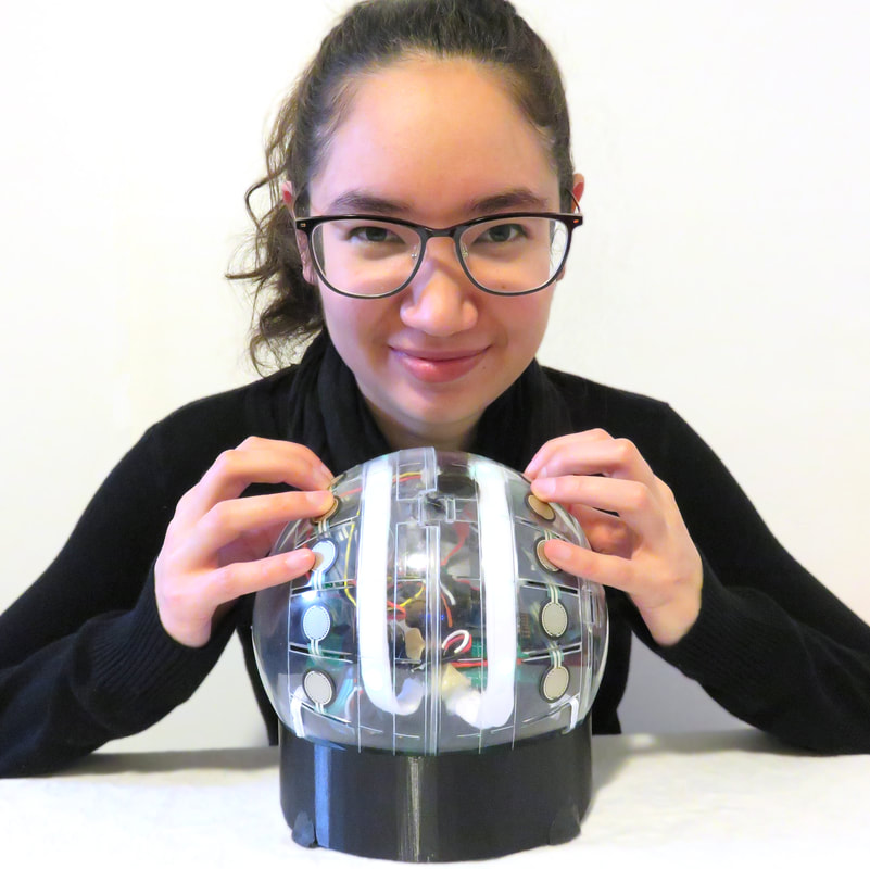
|
 RSS Feed
