|
The skipped data issue with the Arduino has been solved. All I had to do was bump up the baud rate. But I'm keeping my workaround in the Max patch as a safeguard.
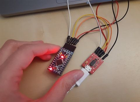
Now the ESP8266 is giving me grief... I woke up with a brilliant idea. What if I solder in headers to the circuitboard for both the NRF24l01 modules and the ESP8266 module. Before I was able to get the NRF24l01 working to send one analog sensor data to another NRF24l01, then the receiving arduino it printing out the data into the computer through the cable. If I could get it to work for all my sensors, then I can move forward with my instrument prototype, solder the circuitboard and take my time troubleshooting the ESP8266. When I am ready for the ESP8266, I can just easily unplug the NRF24l01 and plug in the ESP8266. One problem. The NRF24l01 uses SPI. Previously I couldn't figure out how to use I2C busses to have the LIS3DH work with the TCS34752. That's why I plugged the LIS3DH in using SPI. I tried to figure out how to have two SPI devices, but when I uploaded my code, I did not see any data being sent to the receiving NRF23l01. It is difficult to troubleshoot whether this is a wireless problem or a two devices using SPI problem. I looked it up and I'm not the only one who struggles trying to get the NRF24l01 to work with other SPI devices. Then I thought of another workaround. Before I was comparing the LIS3DH against the ADXL337. I ultimately picked the LIS3DH because it was very exact about its orientation with 1's, 0's, and -1's. The ADXL337 gives more of a loose range for each of the xyz data. Therefore it would require a little more Max programming. However, it is an easy workaround to my problem. It uses three analog pins to send its data, not SPI or I2C. So it would not cause me any grief for making the Arduino sketch work for it and my other sensors. So now I have a new "to-do". 1) Test the simple ADXL337 example code to be sure I want to go with this workaround. 2) Make sure I am able to use this with the rest of my sensors, and the mux through serial. 3) Combine the giant sketch with the NRF24l01
0 Comments
I multiplexed successfully and combined the sketch with the LIS3DH and the TCS34725 sketch! So now I have the capability to send all the sensor data I want to Max over serial. I just need the sensors and the multiplexer to arrive in the mail to actually do it....
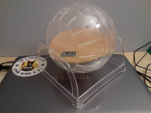
There is one problem though. Sometimes sensor data in the string gets dropped. Like it would print out perfectly 18 or 20 times, then one or two strings would only have the data from on or two sensors. Then it would go back to normal again. I think this has something to do with the arduino sometimes not reading all of the sensor's data fast enough before sending it out over serial. I made a workaround in Max with a [zl.len] object and a [gate], where it does not let the string through if it does not meet the minimum length. When I have the arduino set to print out the data as fast as it can (within milliseconds), the skipped strings are not noticeable for the purposes of music making. But that doesn't solve the problem, it's just a workaround. I've posted in the arduino forums to see if anyone can think of a real solution because I'm stumped. Neopixels are cool. I have a WS2812B strip that I was saving for a different passion project. And then I thought since I'm using a colour sensor, it would be really cool if I could add the lights to the hamster ball in order to have some visual feedback of what colour it is sensing. (of course I would use a light diffuser and a separate battery to power the LEDs). I was able to successfully combine the arduino sketch that changes the LED colour with the colour sensor, with the sketch that I previously made with the multiplexing, accelerometer, and colour sensor. However this caused a new problem. 1) I had to print extra HEX colour data to drive the LEDs, and that messed up my beautiful strings that Max could understand. So it prevented any sensor data from getting to Max properly. 2) The Adafruit Neopixel library slows down printing any sensor data to approx once/second, which is way to slow for making a musical instrument. I searched the problem and I'm not the only one with this issue. So for now, the idea to add the LEDs is on hold. I do have an idea that probably will work. It's where I have the mux/LIS3DH/TCS34725 sending their data to Max like before. And then make a Bpatcher that sends colour messages from the colour sensor to another arduino that has the LEDs setup. I did a quick search to see if other people have tried to drive these LEDs with Max, and lots of people have: https://cycling74.com/forums/connecting-led-light-strip-neopixels-to-max/ But this will take extra time to figure out, so it is better to just continue making the instrument as planned without the LEDs and if I have time, then figure out how to add the LEDs. Now I need to get this baby wireless! I initially had hooked up the LIS3DH via I2C and for the past couple days I've been trying to figure out how to write in the arduino code to handle two I2C addresses. Something that is so simple and used a lot, yet I couldn't seem to properly convert example codes of other sensors and LCD screens to my sensors. Well I was looking at the Sparkfun hookup guide for the LIS3DH again and noticed that it also has the capability to hook up via SPI!!!! So I figured out how to do that, then combined the TCS34725's I2C sketch with the LIS3DH's SPI sketch and voila! I am getting sensor data from both! It still bothers me that I couldn't get the multi I2C going because I think that's important to understand. But now that it works I can at least move forward with my instrument. Also, I read online that people think SPI is better than I2C because it's faster. Although, it does take up more digital pins, and means more circuitboard soldering for me. I had previously figured out how to combine the analog pin 16 channel multiplex with the LIS3DH, but that was the I2C version of the ardiuno sketch. Now I need to go back and combine the multiplexing sketch with this new colour sensor + accelerometer sketch! :) 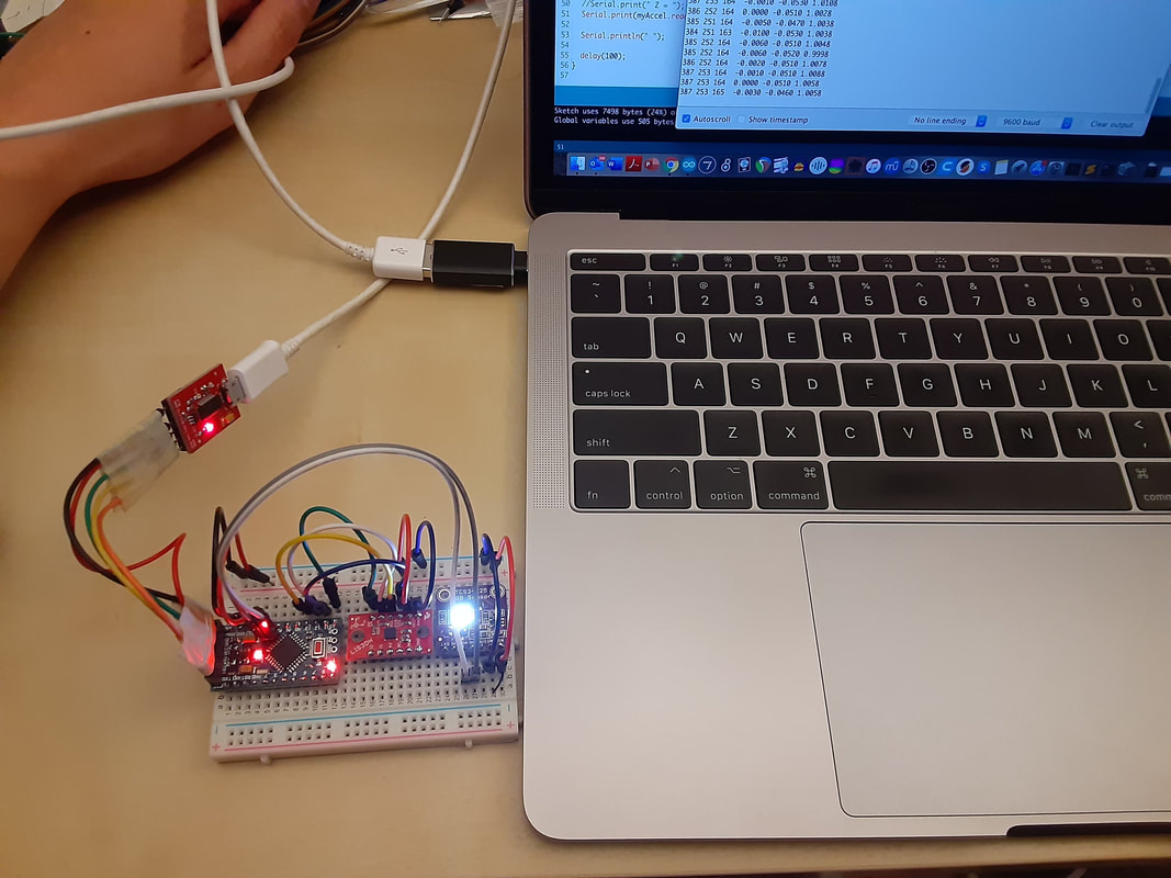 Every time I think I've ordered all the parts I need, I realize I still need another part.
I decided to give up on the NRF24L01. Not that I couldn't get it working, I could, but I want the potential to have multiple transmitters and I kept running into problems. I noticed in the arduino forums that I'm not the only one who wanted to try it and then gave up on it. I have one ESP8266 sitting in my stash. I didn't want to use it because I feared that I would run into the same router problems as the MKR1000 if I tried to use multiple arduinos. But I also saw that it has a function to make a network in and of themselves, so my previous arduino network idea still may work. I think it would be easiest to for now program it to just send UDP packets, like the MKR1000, and then afterwards if I have time, figure out how to make a multi esp network. I realized that I have a few 8 channel analog multiplexers, but my total number of analog sensors will be more than 8. I ordered a 16 channel mux. Even though it hasn't arrived yet, I downloaded an example code, tweaked it, and added the LIS3DH to it. That way I at least have the code done for the IR sensor, FSRs, and the accelerometer. Even if I can't figure out how to combine it with the colour sensor, that's still plenty to work with and make into a complete instrument. I really hope I can get the colour sensor working with everything else though. I also have an LED strip that I was saving for another project, but I thought it would be really cool to add it to the ball, and have it change colours based on what the led strip is sensing. I will have to come up with a way to diffuse the light though so the players aren't blinded... I also realized that all of my sensors are either 3.3V compatible or both 3 and 5V compatible, BUT the IR is 5V compatible only. I tried hooking it up to the 3.3V output to see what happens. It still works, but not as great as it could be. I want to use my Arduino Pro Minis for this project and the ones I have are only 3.3V. I ordered a level shifter to hopefully help. After ordering more parts from Elmwood and BC Robotics, I realized I need a JST switch to turn on/off the battery because it would be difficult to unplug wires while inside the hamster ball. Sigh... I have another bad breadboard. :( The time of flight sensor works! What happened was the distributer gave me the wrong sensor! The Pololu support worker recognized the difference in a picture that I took. All I had to do is download the correct libraries and it's perfectly fine! Distributers shouldn't be handing out wrong sensors... grumble grumble... Things that I noticed about it:
Started thinking about how to put this all together. I'll need to figure out:
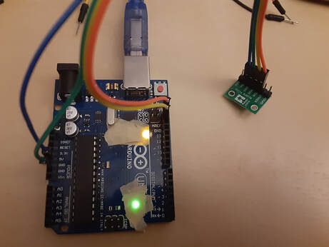 
I figured out pretty quickly that I had the wrong kind of FDTI adapter for my Arduino Pro Minis. So I went to Solarbotics to pickup a Sparkfun one. And it works! But only if I plug it into the back port on my laptop. If I plug it into the other port, it is not recognized weird! But, the good news is, I'm able to program my Minis and they all work!
I have two different tilt sensors, one I found among my stash of goodies and I'm not sure where it came from. The other I ordered from Solarbotics before I knew that I actually already had a tilt switch. When at rest it output 0s. When I tilted it, it was supposed to output a 1, but instead it spat out several 1s in a row. That's ok, by what I can tell, it can still be used for detecting shakes/tilts very well. It might be good to combine it with a very jittery, annoying IMU that does not go freeze when at rest. Although, this depends on how it is used and played with, as it might actually not be a good idea, depending on how it is played.
I also compared my two triple axis accelerometers: LIS3DH and the ADXL337. The LIS3DH was very jittery, similar to when I used the LSM9DS1. It plugs into the SDA and SCL. When I saw what it was doing in Max, it was mostly giving me approximately 1, 0, and -1 for each axis. I added the [round] object to make it exactly 1, 0, -1. It made me realize that I should go back to the augmented props that have the LSM9DS1 and see if the [round] object would improve them. Since the data is jittery and it is a very small range, I would not recommend this sensor if you want to get a smooth range of data. The ADXL337 was a little jittery, but not too bad. It probably could be smoothed out with some averaging. It's raw data was approximately around the 300s. It plugged into 3 analog pins, one for each axis. So I wouldn't recommend this sensor if you need a lot of analog pins for other sensors. It isn't as clear about which axis is turning, or when it hit each 45 degree angle. But it gave more of a range of data for each axis, so it would be better for that. April 6 Edit: I don't know what I was thinking about the LIS3DH. It works great. It just hasn't been my day today. I have a VL53L0X Time of Flight distance sensor (400cm max) and tried hooking it up. When I do, it shorts out my Arduino. As soon as I unplug the sensor from the 5V, then the Arduino comes back alive. Super weird! I was going to post on the polulu forum about the problem, so I unplugged the sensor from the breadboard and hooked up some jumpers in order to turn it around and take a good picture that shows the pin labels. When I plugged it in with the jumpers it was fine! So maybe something was wrong with my breadboard. I uploaded an example sketch, but it was unable to detect the sensor. Maybe I fried it. :( I tried making a simple IR break beam with an emitter and receiver. I followed this tutorial: http://elonics.in/breadboard-projects/infrared-ir-proximity-obstacle-sensor-using-lm-358 The sensor was constantly 1023 and didn't move from there. Maybe there's something wrong with the parts I got too. I have a pack of hall effect sensors; the OH49E. I couldn't find a tutorial that's specific to this kind, but I found this one: https://maker.pro/arduino/tutorial/how-to-use-a-hall-effect-sensor-with-arduino When I put a magnet against the sensor, nothing happens. But if I unplug the ground, then it prints a "detect". Not sure what's going on. 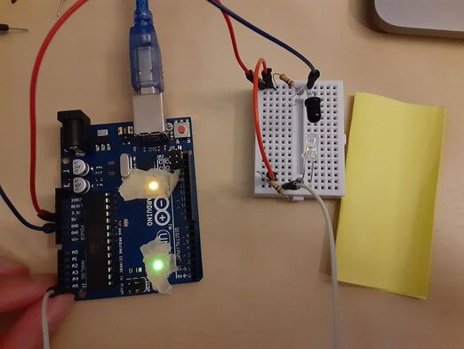 I compared the Sharp IR Distance Sensor (4-30cm) and the Ultrasonic HC-SR04. It is night and day difference!
I used the ultrasonic before for an old dance sword hobby project. It's annoying to program for because you have to write code for the trig and echo pins. The ultrasonic is also not as reliable. I find the when I put my hand in front of it, it doesn't register it as easily as something with a larger surface area. It jumps back down to 0 a lot when it misses my hand. Even when it is catching it, the data jumps around a little too. The Sharp is beautiful! It's so simple to program for. When I map its data to a slider, it feels like when I move my hand up and down, it is exact! It very easily and effortlessly tracks my hand gestures. The IR sensor also works through transparent and translucent plastic. Although, the less transparent it is, the more jittery the data. As expected it works in the dark. Now that I compared them, the only reason why I would use an ultrasonic instead of an IR is if I'm on an extremely tight budget, or I want to track whole bodies at much farther distances. But even then, there are more expensive Sharp IR sensors that have a farther distance threshold. The problem with those is that you completely lose the short distance range. For example, there is one that's range is from 20cm-150cm; close range is lost. I also have a Time of Flight sensor, Hall Effect sensors, and an IR Emitter/Receiver that I would like to test out. But for now, goodnight.... Today I did what everyone wants to do on their days off from work. I went to work. For context, right now I'm employed at a makerspace at UCalgary. I needed to 3D print a case for my Zoom audio recorder and I get paranoid if I leave the printer for too long because that's always when it takes its opportunity to fail. So I packed up all my sensors that I wanted to test out and worked on them in the makerspace. I started with plugging in one of my Arduino Pro Minis. The LEDs light up when it's plugged into the computer. But I downloaded the drivers and it wasn't being recognized at all on the ports. Either the board is dead right out of the box, or my FTDI adapter is dead right out of the box. I will check with my other boards to confirm. I ordered 6 of them, so I doubt all 6 are duds. I setup three different colour sensors to compare: APDS-9960, AS7262, TCS34725. My APDS-9960 was dead out of the box, so that's a shame. That's the cool one too with gesture sensing :( The AS7262 is the one that gives 6 bins of colours. The LED on it was broken (or there was something else I had to do to get it to work...? I followed the adafruit hookup guide though...). So I setup an LED to shine right next to the sensor and it made it work a lot better. I liked the TCS3472 the best between the two because (other being fully functional) it seems to be more distinct when showing the difference between RGB than the AS7262. That clarity is important when programming for instruments. It also works when you put a transparent plastic in front of it, so that's good to keep in mind while making! Photo-resistors are also dumb. All of mine work, but it's impossible to set a consistent threshold on them. When I try to cover them completely, the values are not within the same ballpark each time. 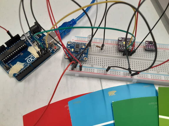 My thesis is to consider the limitations and affordances of different sensors first in order to come up with new concepts for new DMIs; in particularly Alternate Gestural Controllers (Miranda and Wanderly, 2006). So it is the opposite of having a design problem or design concept, then trying to think of what sensor to use to make it.
1) I started with going through the Adafruit website and copying details of each type of potentially useful sensor into charts. There were colour/light, biosensors, sound, IMUs, proximity, touch, and raw materials and textiles that could be turned into analog sensors. I ignored environment related sensors, such as temperature, barometric pressure, and moisture sensors, because I want to focus on sensors that measure human input as opposed to environmental input. Technically light sensors/photocells fall under this category of environmental, but light is easy for humans to directly, or indirectly manipulate it. Same with colour. 2) I then took each of these sensors and categorized them by their affordances and limitations. 3) I then made a Max Patch that output a random name of one sensor, two sensors, three sensors, or four sensors (based on which button is clicked). I didn't necessarily need a software to give me these lists of random combinations of sensors. However, I found it made it easier to constantly have to think about new groupings that I don't necessarily expect. That way I don't think too long about any single sensor and the ideas are less likely to become stagnant. I made a spreadsheet of ideas of new DMIs with only one sensor, two sensors, etc. While coming up with ideas, I had a rule that I could conceptually use as many of one type of sensor as I want, just as long as I utilize every sensor that was listed in the Max Patch per DMI. I found that when I was coming up with ideas for 1 sensor DMIs, I had many ideas per sensor. I also took note of which DMI concepts could be made with alternative sensors. For example, IR distance sensors, ultrasonics, and time of flight sensors all work very similarly and the main reason of using one over the other is the distance of their sensing range and possible interferences. My best ideas for the 1 sensor category I intuitively wanted to add more types of sensors. So in terms of creative flow it went from: Sensor => limitations and affordances => concept for how it is interacted with/attached to an object/gestures => add more sensors to existing instrument design. When I moved on to the 2 sensor chart, I only had one or two ideas for DMIs for each combination of sensors. When I got to the 3 sensor chart, there were times where I felt stumped as to what I could make with some combinations. Sometimes two of the sensors given were similar enough that it would be redundant to use both of them in one DMI, or it didn't make sense to combine them given their limitations, such as resistive touch screen, acceleration from a phone app, and leap motion. Other times one type of sensor could create interference for another type of sensor. And sometimes I couldn't think of any ideas other than a DIY MIDI interface. I left those blank. The difficulties for coming up with ideas increased with the 4 sensor chart, with much more combinations of sensors left blank. Interestingly, some of my favourite ideas use multiple different types of sensors. It would seem that it is much easier to start with one sensor, then think about what other sensors to add to it than to be given a handful and figure out what to do with them. My favourite ideas I sketched out on paper and listed the sensors, and what group the sensors came from (1 sensor, 2, 3, 4, or spontaneous other) I'll add the charts to this blog post after I cleaned them up. |
Welcome!If you are looking for a summary for my Masters thesis, it is here. Archives
November 2022
Categories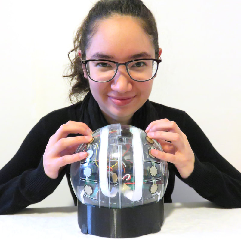
|
 RSS Feed
