|
I started to organize my Arduino to Max patch a bit. The RGB values I actually changed the background colours of the float boxes to RGB. I changed the accelerometer data float boxes to light blue. And I changed the IR data box to purple. The order that the FSRs data are printed in are not the order that they are laid out on the ball. This is because I went with whatever was physically easiest/closest to hookup, and that's not always the same order as on the multiplexer (this happened with TRAVIS I and II too). I first organized the layout of the FSRs data in the patch to match the physical layout. This is how it matches up: Right Side: FSR1 = S1 FSR2 = S8 FSR3 = S2 FSR4 = S7 FSR5 = S3 FSR6 = S6 FSR7 =S4 FSR8 = S5 S13 is always a little high when at rest (~450-600). There is an issue with four of the FSRs, mostly on the Left side, in that they bleed into each other.
I thought of taking out the circuitboard and going over the connections again. However, I am sure that all the connections were fine when I tested with a multimeter. Also, I risk making the situation worse and it was very difficult to get all of the sensors plugged in in the first place. I detached the FSRs on the left side that were bleeding into each other and re-arranged them so that the three on the left side are all close to each other. When I moved S16, when I re-attached it, it now sits higher than it was previously when it is at rest. I pulled it off, then put it back on again and then it was back to the way it was. Since that fixed it, I tried the same thing with S13. When I pulled it off, the data went down to where it should be. I think this is because part of the tail of the FSR was bending in a way that it shouldn't and pulling it off the ball straightens it. However, every time I tried re-attaching it, once I press on it again, it would go back to resting high. I'm just going to have to deal with it in Max. The new arrangement is as follows: FSR9 = S13 FSR10 = S11 FSR11 = S14 FSR12 = S15 FSR13 = S16 FSR14 = S12 FSR15 = S9 FSR16 = S10 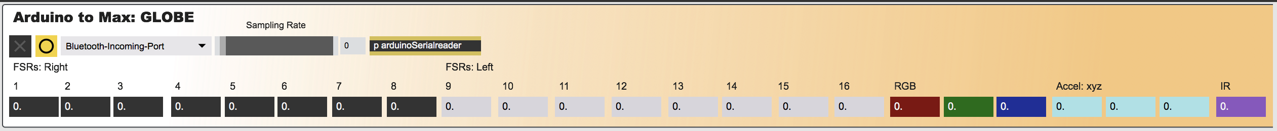
0 Comments
Leave a Reply. |
Welcome!If you are looking for a summary for my Masters thesis, it is here. Archives
November 2022
Categories
|
 RSS Feed
