|
This weekend I divided and conquered with my genius significant other, Kevin Mitchell, who just so happens to be a software engineer. I worked on my Max patch for the piece while he worked on tweaking the arduino code for the ESP8266 so that Max could send messages to it to control the brightness of the LEDs, but the colour sensor still controls the colour. At first he was having troubles with memory on the ESP, so when I sent a message with ramping values from 0-255 within 5000 ms the ESP freaked out mid way and reset itself. But he figured it out how the flushing worked and now it's working without explosions. In the upcoming piece I plan to make the LEDs audio reactive by having them turn off/on to the beat of the music.
Here are videos to demonstrate. The first is of it not quite working. You can tell when the LEDs suddenly flash and then turn off. The second video is of it working well and Kevin was clicking the button to rapidly turn the LEDs off/on quickly.
For my piece I've been working on getting binaural audio setup. And I tested the different sections with the GLOBE. I figured out that if lets say you have a playlist object that is playing, and while it is playing you change its start/end points that it loops, it will not jump to the new points, even if what it's playing is outside of its start/end points. For example, sending a message that says: [selectionms 0 86450.139046]. So for my looping sections, instead of having just one file to loop different parts of, I have to go back to Logic, cut the sections, re-import each section into Max, and fade in/out the parts when I want to transition.
I am also working on building a new spinning stand. Well the actually metal piece of it that the GLOBE attaches to was bought as part of a set for another hamsterball brand. But with my dad, we cut a piece of wood, sanded, primed, and painted it. Now we just need to bolt the wire stand piece down to the wood. This will hopefully give it more weight and make it so I don't have to hold onto the stand while playing like I did for the Etude. Here is just the plain acoustic mix of what I plan to use as the base material for my piece:
0 Comments
I'm currently slowly working on a new piece with interactive visuals. It's been nice working without a deadline instead of rushing to push out a piece in under two days (not that I did that too often out of necessity during uni, that's just how fast I worked when I had other strict deadlines to work on as well. I can generally work in Max faster than other things). I'm really forcing myself to take my time with it.
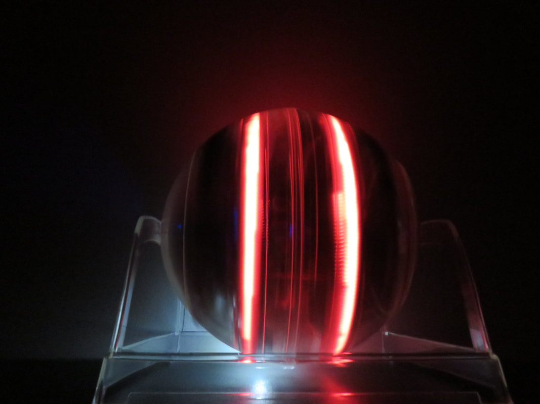
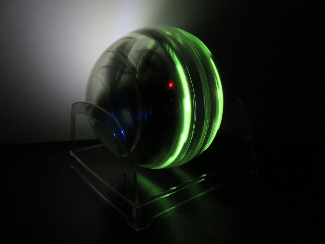
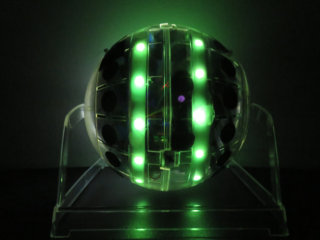
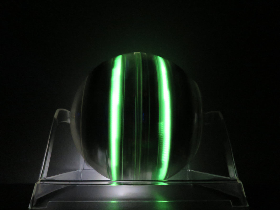
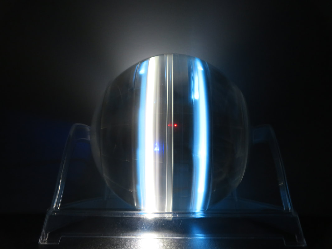
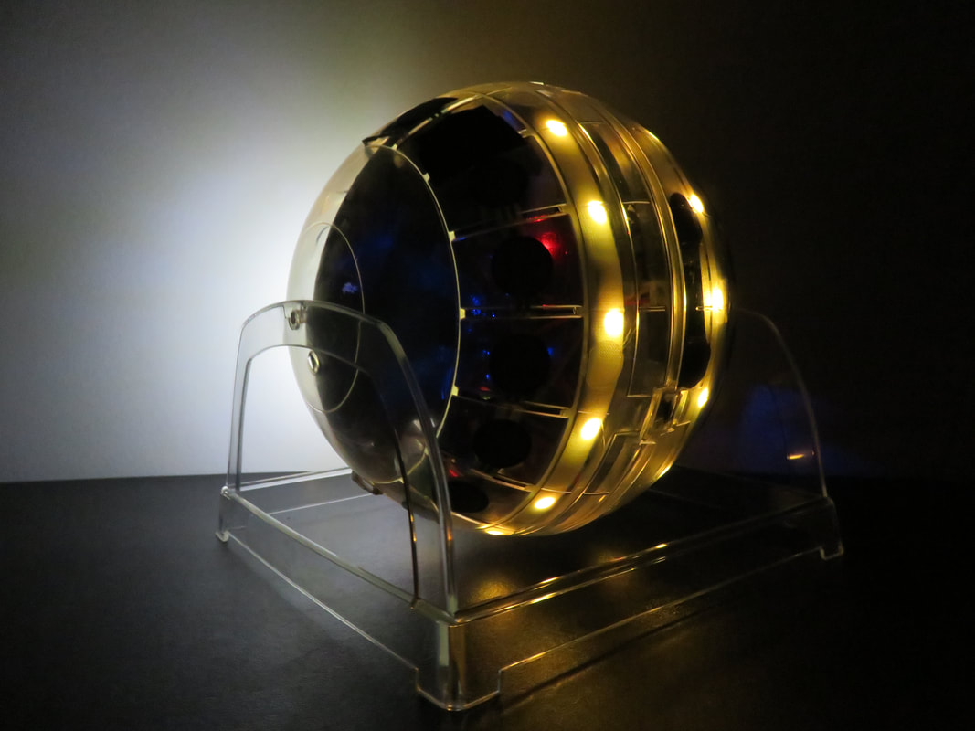
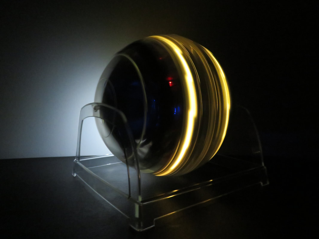
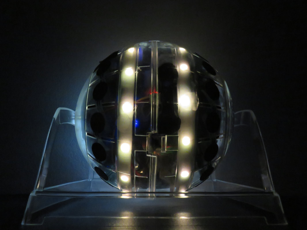
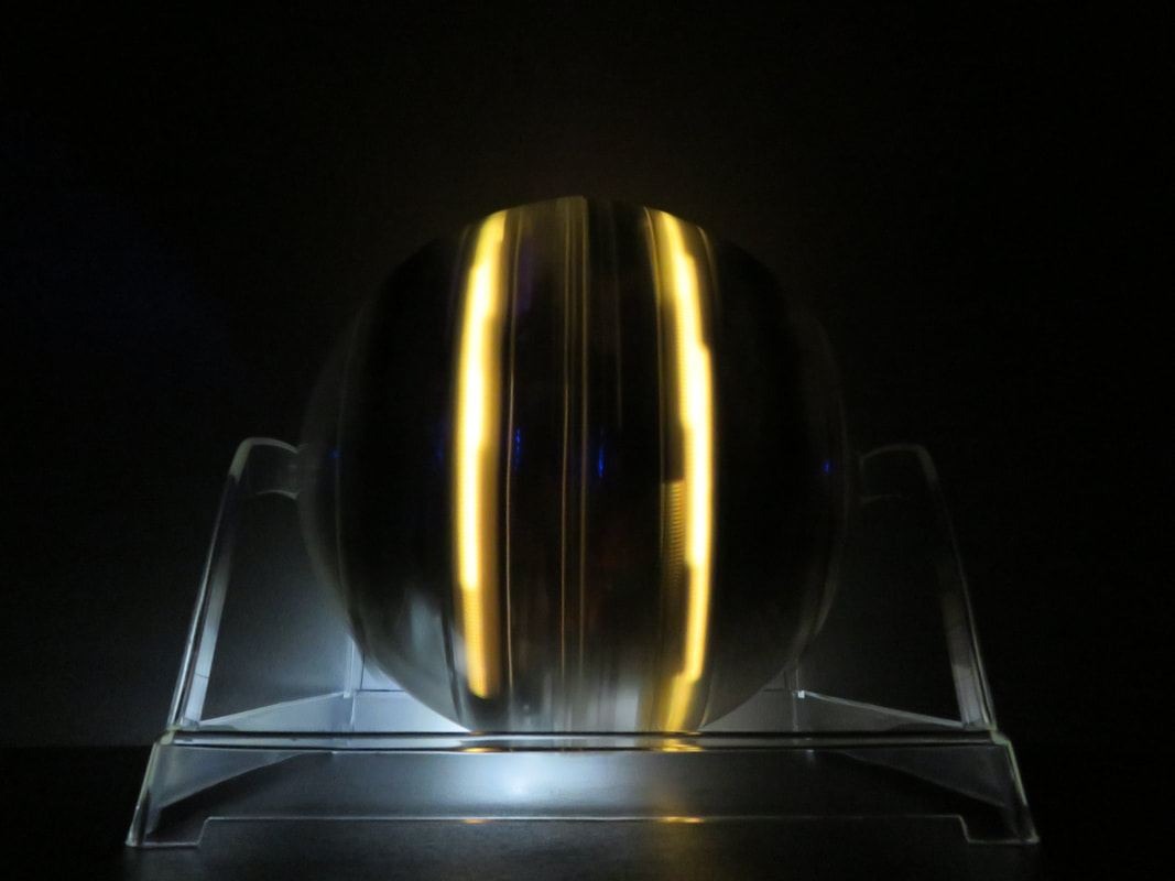
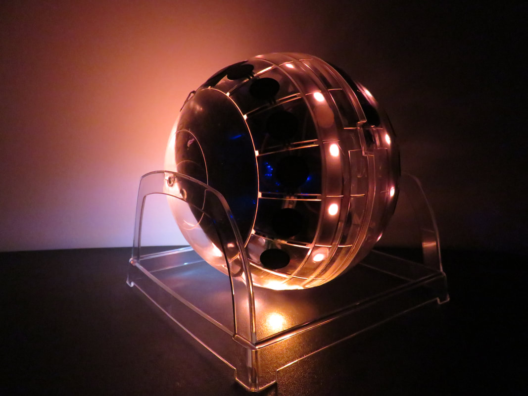
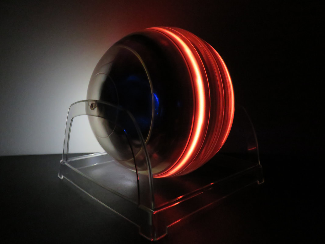
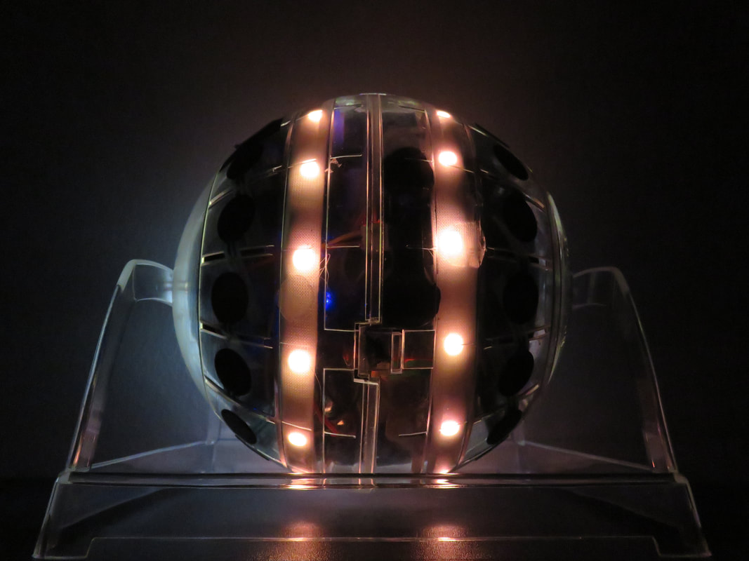
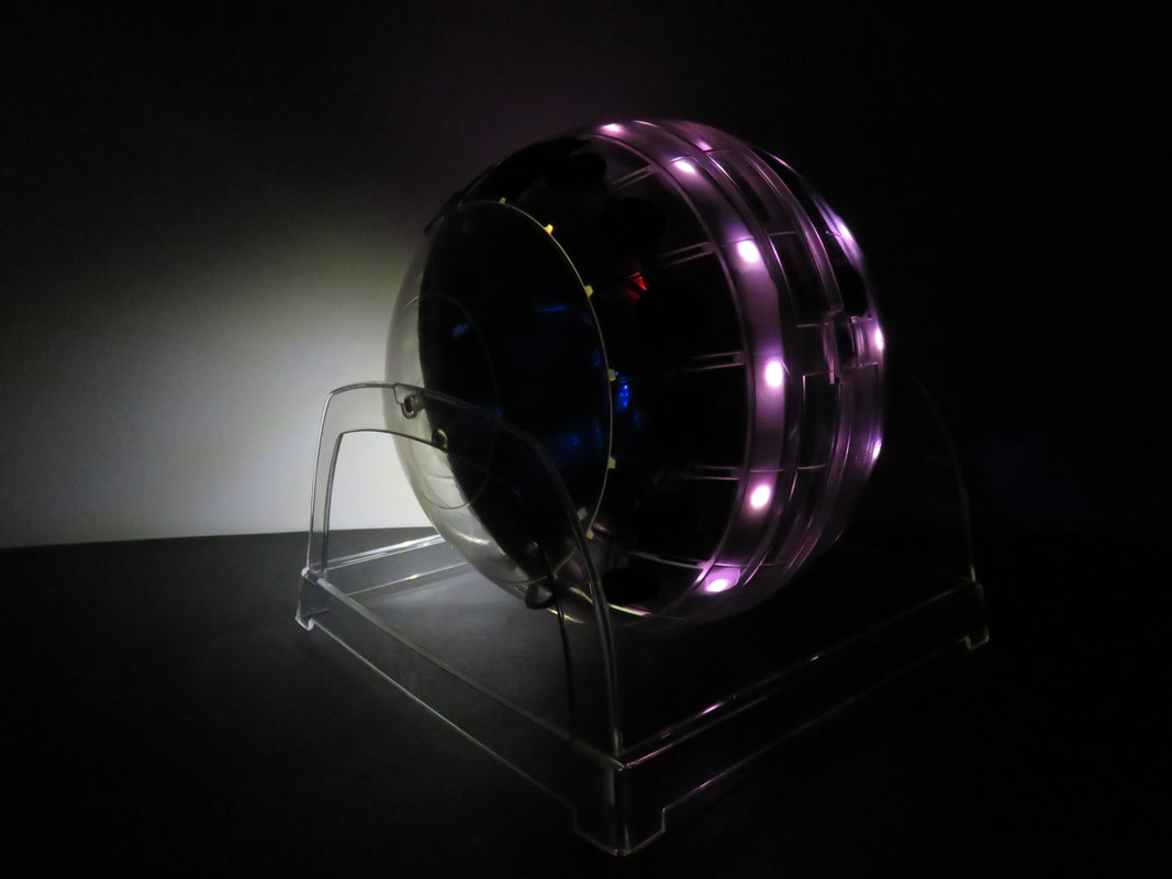
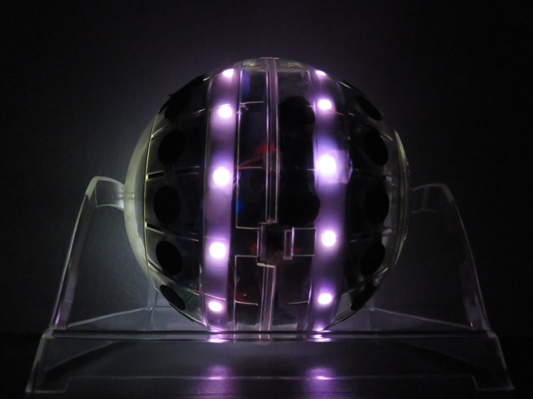
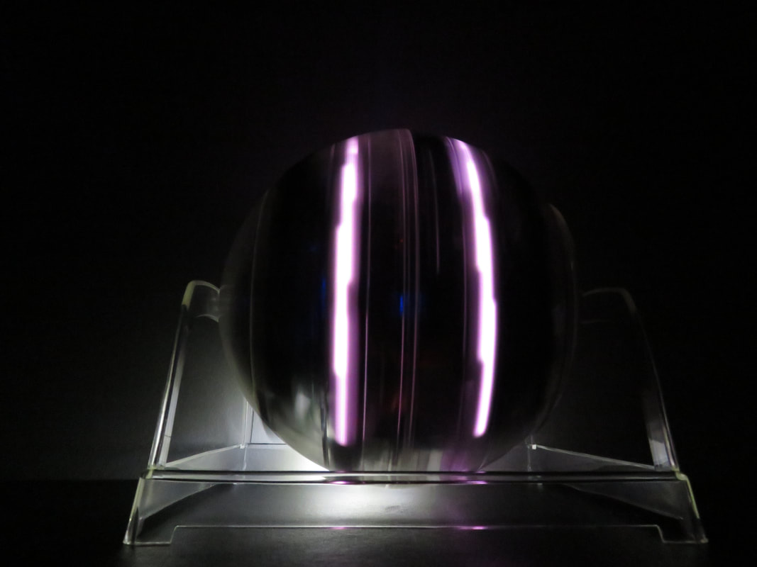
I have a bunch of side projects going on right now too. I'm currently working on a modular sword, which design is somewhat based off of my previous work for the augmented props. There was something I discovered for this project that is related to the GLOBE, so I thought to take note of it here. I am using the LIS3DH accelerometer for both of them. For the GLOBE I am using one analog input on this sensor (the IR sensor). Whereas for my new project I was planning to use all three. I found that no matter what, the A3 pin just refuses to work. It's completely unresponsive. I then unplugged the sensor that I had used on the GLOBE and tested it in case if was just a bad sensor that I was using before. Nope! the A3 pin does not work on both of my accelerometers. I suppose I didn't notice this before because for the GLOBE, I only had to use pin A1. I've tested this both with a breadboard, plugged into different spots on the board, and with just jumper wire connectors. It's consistent. For the new project I am using an ESP8266 Wemos D1 board. That is the only other difference. When I get a chance I should test this accelerometer on another board to see if it makes a difference, though I doubt it will. I don't remember if I had tested this with the GLOBE on the ESP8266 HUZZAH Feather. I'll probably get around to doing that later. This shouldn't affect my project though, there is still the one analog pin available directly on the board that I could use instead. And if I decide to add more analog sensors then I'll just multiplex it. If pin A3 is consistently not working on other boards though, that really sucks. That means there is one less analog pin available to potentially use on the GLOBE (not that it really needs another... or does it...? ). Edit: I tried now with a button hooked up to all three analog pins and that didn't help. I tried using an Arduino Pro Mini (3.3V) and still no response from the A3 pin of the accelerometer. It just sits around 508-514. I am out of ideas :( PS: I looked at the info on Sparkfun again for this accelerometer and on the table for the pins it says for A3 "Analog in (unused for temp readings)". The other two are just "Analog in". I don't know if that has to do with anything. I had an idea for more pictures in the dark in order to really show off the cool colours from the LEDs. I feel like I spent a lot of time yesterday practicing for the hamster stand piece, so today I decided that each day I'll start with practicing the twister mat piece first so it doesn't get neglected. I think the tendency to practice the hamster stand piece more is because its mapping is more similar to that of a traditional instrument; it has exact pitches and timbre to worry about and a historical understand of what its sounds should sound like. AKA There would likely be more understanding and criticism from an audience about what would make it sound "good".
I found that instead of trying to memorize which FSR is mapped to which specific note and trying to think about music theory and chords while I am playing (something that I can't do very well with violin either), it is easier to think of how many FSRs are in between the two that I'm playing. One FSR in between are the easiest to visualize and they are thirds. Then I think about two FSRs in between, then three, ect. Thinking this way helps me make more "musical" decisions in the moment than to think about perfect 5ths, 4ths, 6ths, etc. So today with the twister mat practice I realized that it is difficult to remember exactly what is mapped to what with the accelerometer and the IR sensor; it's different for each colour. I realized that some colours, like green for example, used only the X axis of the accelerometer, and others used only the Y axis. This is more challenging to remember, so I changed it so that whenever there is only one axis mapped, it is the Y axis. I have a preference towards the Y axis because of how the FSRs and IR are oriented. I also realized that some playing techniques are more preferable than others depending on the sound engine. For example, I don't like how it sounds in the yellow when the ball is upside down. But I love it when the ball is upside down when it is green. I like to roll the ball around on the ground a lot when it is red, but not so much with the other colours. I dug deeper into why the green on the twister mat has been so difficult. I found that it is being recognized fine, but the gate, controlled by putting a threshold on the clear, has been closing before the trigger for the green can get through. Then it would not change back to green once it can get through because the green's onebang would then need to be reset (because it already fired off). I improved the situation by
1) Add a [pipe 100] to the integer that turns off the gates (but left turning on the gate at its regular rate. 2) Have the "off" always resets the green [onebang], even when it is turned off for therest of the colours. Now it seems a little too easy to accidentally trigger green when "off" is selected. But that's better than it not being sensitive enough. Luckily the sounds on green are my favourite for this piece. And with practice I know tricks to help prevent it from misfiring so it shouldn't be that bad. Since the colours on the twister mat are so dark, I added a brightness function to turn up the colours a bit. Basically, you know it's where it needs to be if when you sample white, it is white. I practiced on the hamster stand patch a bit too. I tried everything I could think of to reduce the latency that Graeme noticed on the FSRs, but I couldn't make any noticeable difference. It's funny that I'm not sure if I noticed any latency before on FSRs, but now that it was pointed out to me I definitely notice. I checked with the old demo patch and I think the latency is there too. I've been working away trying to make the colour detection even more reliable. I added [onebang] to the colour detection and delays on resetting the [onebang]s so that it doesn't misfire as often. In general I'm still having the most troubles with sensing green on the twister mat. I realized the best playing technique with the twister mat is to roll the ball around to the colour I want, and once it is sampled, then lift the ball up off the ground to prevent it from accidentally selecting the wrong colour when I don't mean for it to.
I noticed that it is difficult to audibly tell how the accelerometer is affecting each colour section. I went through each and decided to make sure that the IR is very noticeable. That way I'm mostly focusing on the IR and FSRs during the performance and I just let the accelerometer do its thing, whatever that may be. I'm considering maybe putting another filter on just before the master gain so that there is one unifying parameter for the whole patch. Not sure if it is a good idea or not. Oh, and I'm allowed to have my brother be a guinea pig. Yay! I took out the function1 in the Arduino Code and made the "clear" print through both serial and UDP. It really does act like a proximity sensor and makes it simple to get the colour sensor to ignore sensing ambient light. It will be helpful in that I don't have to sample the ambient light for my twister mat piece, and make it so it more accurately recognizes green. (hopefully, I still need to test).
I also realized that in order for the data to print through serial, the ESP8266 has to first make the wireless connection. The router can be unplugged after the connection is made and the ESP8266 can still print out the data through serial, it just needs the initial connection. This was the same with TRAVIS I. I figured out that what is happening, since it couldn't connect to the network, it was stuck printing out "..........", which is what it is supposed to do. If I commented that part of the code out, then it works fine through serial without having to first make a wireless connection. The only downside is there is now nothing to show me that it is clearly a wireless issue. However, the dots wouldn't show clearly in Max regardless, so it doesn't make a difference for how I'm using it. Since I took out function1, I renamed frunction2 as function1, and function3 as function2. I am almost finished the patch for my second piece with the GLOBE. Last night I was playing around with it on the twister mat some more. I noticed that it had a tendency to trigger red more often, which was fixed by sampling the ground as "off" and ambient light as "orange". However, the ambient light was very dark, and the green circles on the twister mat is also very dark. So that made it accidentally trigger "orange" when I actually meant for it to trigger green.
I slept on the problem and I remember that there are three functions in the arduino sketch to drive the LED's. They are based on another value coming off of the colour sensor I think it has either to do with proximity or overall light levels. I can't remember, got to check again. But basically it allows the LEDs to turn off if the sensors "sees" black, and for them to maintain their previously sensed colour of the sensors "sees" ambient light. If I can modify the Arduino code to spit out that value, I could use it to program the colour detection similarly, where it will sense a colour if it is close and ignore if it is ambient light. I also thought it would be good to take out that LED turn off function in the Arduino code to better reflect what is happening with the sound. |
Welcome!If you are looking for a summary for my Masters thesis, it is here. Archives
November 2022
Categories
|


 RSS Feed
