|
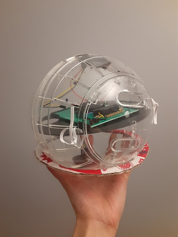
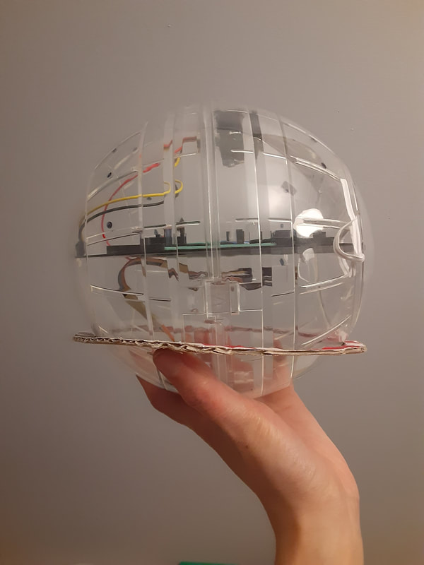
Today I was supposed to work in LabNext. But now most of the workers must work from home. Which means no more 3D printing from LabNext. I went to the fablabx to 3D print a stand for the ball. It may be my last 3D print until I eventually can afford my own machine. While I waited for it to print I soldered the wires onto the FSRs. At first I thought I would use heat shrink wrap with them, but then thought maybe that's not such a good idea with the plastic ends. I'm so close to finishing the physical side! While here I also moved the augmented props back into the iLab. I don't know when, if ever, we are going to do a show with them and I wanted to make sure my colleagues could access them if I leave Calgary before we are through this pandemic :( 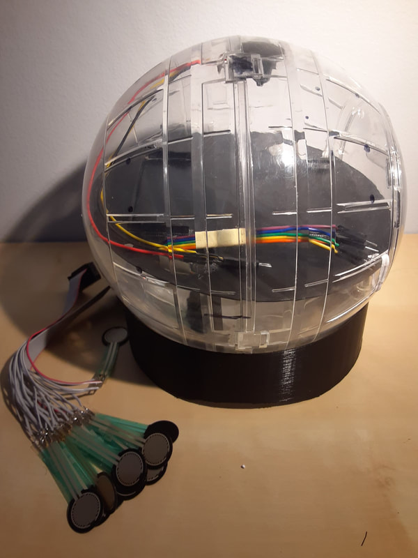
0 Comments
The COVID-19 pandemic has officially affected my thesis, my work, and my personal life. Alchemy Festival is cancelled, I am no longer able to have participants test my thesis instrument, I'm working from home for both my TA position and for LabNext, and even if my paper does get accepted to NIME, the university of Calgary has banned all international travel until September (although, that to is likely to get cancelled). I don't know how I'm supposed to do a public performance with my instrument, because that is a requirement for me to graduate. I modeled a 3D printed stand for the ball to sit in, but I don't know if I'll be able to 3D print it. Maybe I can get creative with some paper mache...? I really just need my own 3D printer at this point. On the bright side, I made some big progress in making my instrument! I successfully got the multiplexer wireless! Now I just need to figure out how to do it for the rest of the sensors. I used sugru to stick the colour sensor and the IR sensor in place. I glued the battery holders on the back side of the disc. I added a switch so I can turn the LED on the TCS34725 on/off. But it requires taking the lid off of the ball and reaching in to the circuitboard in order to switch it. I also added a couple other things to the circuitboard that I realized I previously missed. I planned out where the FSRs are going to stick to. I measured the neopixel strips more precisely to the ball and planned out how they're going to attach. I got permission to borrow the hot glue gun from work. I finally finished marking in class essays and am now back into thesis work.
Due to COVID-19 I've been advised to not get participants to test my instrument. And I just got my first participant to sign the consent forms the day before the university closed (on friday the 13th of course!) :( I asked the polulu forums about changing the time of flight address. Their response is it can be done and to read a specific section of a confusing datasheet. But they warned that since the TCS34725 cannot change its address, there could be issues. Since it's confusing to begin with, and has a risk of not working after all, and I don't know how long it will take for the I2C multiplexer to arrive in the mail, I decided to not use the time of flight sensor for the prototype. I still may add it in the next upgrade though. Trying to get all the work done that requires a makerspace ASAP. I 3D printed battery cases that I will glue onto the back of the disc inside the ball. I 3D printed a little case for the time of flight sensor, even though I'm not sure if I could get it working or not. But I lost the sensor this morning so I couldn't take it with me to measure the case to the sensor. I also sewed tubes to slide the LEDs in to help block the light. I wanted to double layer the fabric, but it was too difficult to sew. If the lights are still too bright, I can dim them more in the arduino sketch, but the dimmer they are, they don't show the true colour as well.
I found the time of flight sensor when I got home. I have made some adjustments to the case and will 3D print it again another time, assuming campus remains open. I posted on the polulu forum asking about changing the address of the time of flight sensor. Apparently it is possible and I'll have to look into it. Of course I find that out after I ordered an I2C multiplexer... I've spent a lot of money for this project on stuff that I end up not using... :( I was thinking last night about how the IR does not work that great with a 3.3V power supply. Also how the time of flight sensor connects via I2C, and that was another reason why I didn't want to use it because I was previously having troubles getting multiple I2C devices working. Well since I now have both the LIS3DH and the TCS35725 working together via I2C, and the time of flight sensor works fine with a 3.3V power supply, maybe I should see if I can get the I2C code working with the accelerometer and the TCS34725. Even though the IR sensor is better than the Time of Flight, when it is powered with 5V, the Time of Flight works better than the IR sensor when powered by 3.3V.
But when I checked its I2C address, it's the same as the TCS34725. I guess I still have to wait until an I2C multiplexer show up in the mail... I started looking at the neopixel sketch and realized that when the data stream slows down, it is when a threshold below 150 or below 1000 is met for the "clear". Those are the thresholds for activating frunction1 and function2. Although I couldn't tell what was in those functions that would be slowing it down. I posted on the adafruit forums asking for help for my predicament with the neopixel strip. And the solution was simple: put the " strip_a.show();" outside of certain loops.
I realize that my babbling about this on the blog doesn't make any sense without seeing the code, but trust me guys. This will be so cool! I GOT BOTH THE LIS3DH AND THE TCS34725 TO WORK ON I2C!!!!!!!!
I realized that the LIS3DH has an example of two accelerometers on I2C. I took that example and altered it for the TCS34725. That's another problem solved! This means that I can finish soldering and be sure of how I'm doing it. I started looking at the Neopixels again. I narrowed it down that when function1 or function2 are called, that's when the data starts printing slow. I don't know why. But I feel a little better that I can tell where in the sketch it's going wonky. It turns out my accelerometer wasn't dead to begin with. The ESP8266 just hates SPI devices. The new accelerometer arrived in the mail, when I hooked it up via SPI it still didn't work. Then I tried both through I2C and they both work! I already ordered a Wemos D1 Mini and checked the SPI wiring with it and it doesn't like it either, and again the I2C method works. I checked again with my Arduino Pro Mini to make sure I wasn't crazy and the SPI method does work with it, just not the ESP8266s.
So now I am left with the same problem again, how do I get both the TCS34725 and the LIS3DH to work wirelessly? I thought of a few things:
Feather
I got the Huzzah Feather working with the TCS34725 + LIS3DH sketch. At least I think it's working. It's hard to tell when I'm working with a dead accelerometer. I found a good example of multiplexing a general ESP8266 with the same 16 channel multiplexer that I have. I think it works much better than the other 16 channel multiplexer example I was trying to go off on before. If I end up going back to the arduino pro mini, then I should look at this example again to get the 16 chan multiplexer going. I tried to combine the TCS34725 + LIS3DH sketch with the 16 channel mux sketch, and that's when things got weird. For whatever reason, the feather only printed the mux sensors and ignored the TCS34725 + LIS3DH. I then tried only mux + TCS34725 and mux + LIS3DH. Neither worked. I then went back to the arduino pro mini to see if the same problem occurred. Pro Mini When I first uploaded the new 16chan mux sketch to the pro mini, the data was printing slower than when it was used with the feather. It was like it was slower to update, or the board has a slower processing speed? I then added the TCS34725 and in the serial monitor I can see that the board found it, and printed it's data for the first line. But then subsequent lines it ignored the colour sensor. For the mux code there is a "while (true) {" inside the loop. I moved it to be before the TCS34725 data, so everything in the loop is incased by this function. And it worked! I then did the same with the LIS3DH. Who knew that struggling with the ESP8266 would lead to me fixing my problem with the 16 channel mux!!!!! :) Back to the Feather Same code, just adapted for the different pins now works for the feather too!!!!! So now in my mind, there is something I need to consider. In a perfect scenario where I can add a wifi module to the Arduino Pro Mini flawlessly, should I use the Arduino Pro Mini, or the HUZZAH feather? In a perfect scenario, using the feather has an advantage because I don't have to interface with another module to make the project wireless. On the other hand, if I can get interfacing between the Arduino Pro mini and a module, that also has an advantage; I could use a 5V arduino, have the IR sensor working at its best, and use level shifters to bring the voltage down for the wifi module and the accelerometer. It would take up much more space on the ciruitboard, but all the sensors would be working at their full potential. I'm just going to have to wait and see when the Wemos arrives on Monday! And now for making the Feather take flight...! So many errors... this is what makes horror movies... At first I thought the ESP8266 01 module gets programed like any other add-on to the arduino: program the arduino with the module attached. But no! These are actually different in that they get programmed separately on their own. Before I figured that out I completely uninstalled and re-installed the arduino IDE on my old Windows computer (my FTDI drivers are messed up on my Mac and I need to do deep computer surgery to fix them. I'm not psychologically ready for that yet...). Of course right after uninstalling the Arduino IDE, my windows chose it was a good time to install system updates which take a few hours to complete... When that ordeal was taken care of, I hooked up my ESP8266 to my arduino to program and got this exact error when trying to upload an example sketch onto my ESP8266: https://forum.arduino.cc/index.php?topic=622116.0 The solution that worked for me was to uninstall the latest ESP8266 Community board drivers and re-install the 2.5.0 version of them. But then I got a new error... The new error was this very common one: https://arduino-esp8266.readthedocs.io/en/latest/faq/a01-espcomm_sync-failed.html Also here: https://github.com/esp8266/Arduino/issues/4414 My solution was to not use the Arduino Pro Mini as a conduit to upload sketches and instead connect the FTDI adapter directly. And then as I was uploading the sketch I got a new error... sigh... 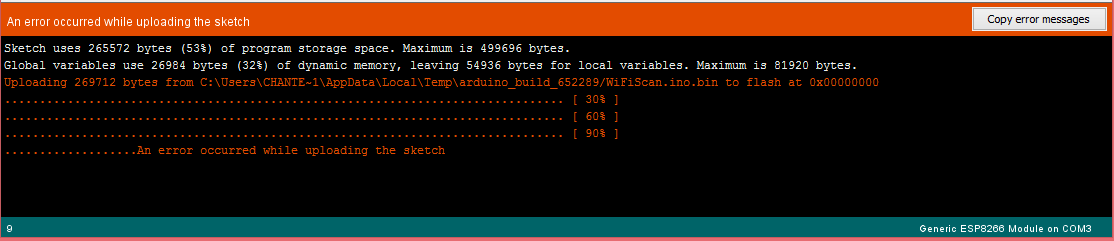 But then I tried uploading again and the previous error came up. I'm starting to feel like this is hopeless! Strangely enough, my HUZZAH feather works perfectly fine. But It only has one analog pin and I was having issues with the 16 channel mux. Also since it's bigger I'll probably have to get a bigger proto-board, if I were to use it instead. :( I then tried increasing the upload speed of the module to 256000. Then I got new errors.... 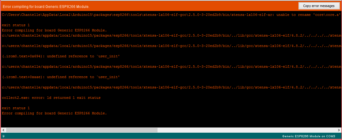 I read in one of the forums that you can upload code to the generic module by selecting the Node MCU 1.0 ESP-12E Module as the board. Aparently they're similar enough that it works. I tried it and the WifiScan code supposedly uploaded. But then when I opened the serial monitor to see if the module was scanning, it wasn't showing anything. :(
I've ordered a Wemos D1 Mini in case if that would work. In the mean time I'll see if I can get by with the feather... :( |
Welcome!If you are looking for a summary for my Masters thesis, it is here. Archives
November 2022
Categories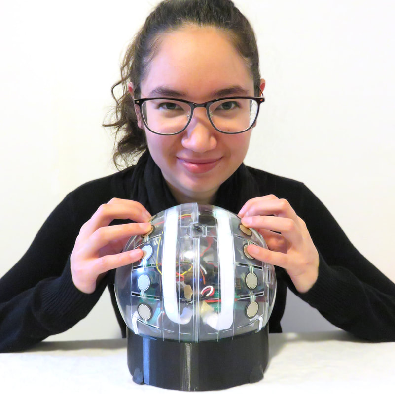
|
 RSS Feed
